


105
BAS-311E.311EL.326E.326EL
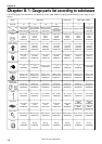
Chapter 7
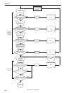
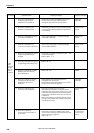
#1.2
No
switches
on the
panel are
not
activated.
#2
If the R/W
switch is
pressed,
the
indicator
lamp is not
lit and an
error code
appears.
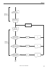
Probable cause
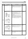
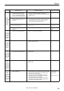
11. With error code [E.c4],
overcurrent has occurred in Y-
pulse motor.
12. With error code [E.c5], the box
cooling fan (at the right when
viewed from the front) is
defective.
13. With error code [E.E0], the [MN]
PROM on the control circuit
board is defective.
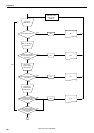
14. With error code [E.F0], the relay
on the power PCB is not
working.
15. With error code [E.F1], the cord
is not securely inserted.
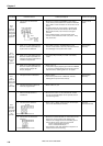
16. With error code [E.F2],
overcurrent has occurred in
power PCB.
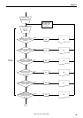
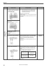
1. Panel PCB is not correctly
attached.
2. Panel PCB is defective.
3. Programmer detective.
1. With error code [E.40], the cord
or the floppy disk drive (FDD) is
defective.
Check/repair/adjust
• Check that connector P6 (YPM) on the control
circuit board is securely inserted and the Y-pulse
motor is correctly wired.
• Refer to #1.1-2
• Refer to #1.1-8 [E.CI]
• Check that connector P25 (FAN-L) on the control
circuit board is securely inserted.
• Check that the PROM of the control circuit board
is securely inserted and its leads are not bend.
• Check that MN and MT of the PROM are matching
those on the main PCB.
• If the PROM has no problem, check the
connection between pin 3 in connector P18
(PANEL) on the control circuit board and pin 5 in
connector P5 (DRV) on the panel PCB.
• Check that the PER code is securely inserted (refer
to #1.1-15). If the error appears, replace the
power PCB with a new one.
• Check that connector P2 (PER) of the power PCB
and connector P20 (PER) on the main PCB are
securely inserted. Check there is no damage in
wiring.
• Find a cause of noise. (Refer to #1.1-2.)
• Replace the power PCB . (Refer to #1.1-14.)
• Check whether the panel setting plate makes
contact with a switch.
• Refer to #1-7
• Pull out the programmer. If a switch is activated,
the programmer is defective.
• Check the connections and pins between
connector P1 on the panel PCB and the FDD, and
between connectors CH1 and CH2 on the panel
PCB and the FDD.
• Replace the floppy disk drive.
Parts to be replaced
Y pulse motor
control circuit
board.
Fan motor
assembly
PRON
Panel code
Power PCB
PER code.
Power PCB
Panel circuit
board
Programmer
FDD Harness
Floppy disk drive
Error status
#1 The
power
lamp does
not light
when the
power is
turned on.