


26 en | Installation MIC612 Thermal Camera
F.01U.249.416 | 2.0 | 2012.09 Installation Manual Bosch Security Systems, Inc.
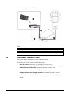
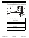
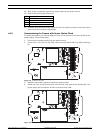
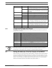
18. Connect the shielded composite cable to terminal block HD3 (and, if necessary, HD6 and
HD7) following the color coding as shown in the figure below, and printed on the PCB.
Figure 4.8 Exploded View of Composite Cable Connections
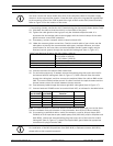
Number Description Cable Gland Size
1Optical Video out M12
2 Composite cable M16
3 Optional switched video output M12
4 Head-end / Telemetry controls M12
No. ID, Connection/
Terminal + Pin
PCB Mark,
Signal
Description/Function of Connection PCB Mark,
Cable Color
1 HD3-1 Power Low Voltage Power (Input 1) / AC supply Red
2 HD3-2 Power Low Voltage Power (Input 2) / AC supply
return
Green
3 HD3-3 RxB Telemetry I/O to RS-422/485 [Rx +]
Full Duplex RxB/Half Duplex Tx/RxB
White
4 HD3-4 RxA Telemetry I/O to RS-422/485 [Rx -]
Full Duplex RxA/Half Duplex Tx/RxA
Yellow
5 HD3-5 0v Ground
[Drain Wire / Shield]
Screen
(Black)
6 HD3-6 TxA Telemetry I/O to RS-422/485 [Tx -]
Full Duplex TxA
Blue
7 HD3-7 TxB Telemetry I/O to RS-422/485 [Tx +]
Full Duplex TxB
Violet
8 HD3-8 Video Video output of optical camera
to Control Room (Coax - BNC CN1)
Core
9 HD3-9 Video 0V Video signal return (optical camera)
(ground to Control Room) (Coax - BNC CN1)
Screen
10 HD3-10 Tamp Sw [Optional] Tamper Switch Black
11 HD3-11 Wash [Optional] Washer Drive Signal Orange
12 HD6-1 AUX1 [Optional] Auxiliary Connection (heater)* Brown
13 HD6-2 AUX2 [Optional] Auxiliary Connection (heater) Grey
14 HD7-1 -- Video Switched Output to Control Room
(Switched visible/thermal video out signal)
Core
(Black)
15 HD7-2 -- Switched video signal ground Screen
(Black)