


20 en | Installation MIC612 Thermal Camera
F.01U.249.416 | 2.0 | 2012.09 Installation Manual Bosch Security Systems, Inc.
example, one of the securing bolts) to the camera’s outside case, and should be
attached to the Earth terminal post on the PCD base of the camera.
– If the system is copper throughout and the camera pictures are fed back to the
control room via coaxial copper cable, then the camera should be earthed only at the
video termination point in the control room. In this case, the "Earth Link" on the PCB
should be broken. Refer to Section 4.4.1 Earth Link on PCB, page 21.
– If the video is transmitted back to the control room via some non-electrical
connecting medium (for example, fiber optic, radio, or microwave link), then the
camera should be earthed at the transmitter point in the power supply unit. The PSU
"Earth Link" may be used for this purpose.
– If dual earthing is unavoidable, then a video isolation transformer should be fitted
between the two earths.
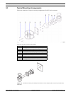
7. Use M8 x 20 mm stainless steel nuts, bolts, and washers to secure the PCD base of the
camera to the mounting bracket. An additional Nebar gasket or suitable silicone sealant
can be used to ensure a water tight seal between the base and mounting surface. Tighten
all bolts securely.
8. Secure all cabling and conduit.
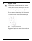
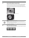
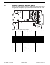
4.4 Installing the MIC Power Supply Unit (PSU)
Each MIC power supply unit (PSU) provides all of the connections needed for power, video,
and telemetry for a single MIC camera. Each MIC PSU has CE and FCC approval and has a
cast-aluminum enclosure that is weather-resistant (rated IP65). Features include:
– A provision for driving various optional interface cards mounted internally to the MIC
power supply enclosure (for example, an 8-input alarm card (MIC-ALM))
– A provision for a signal interface card (MIC-BP4) to connect telemetry to Bosch Biphase
equipment
– Screw termination of all cables (composite, telemetry, and ancillary) into and out of the
enclosure
– Earth isolation and termination within the unit to control video earthing correctly and
thus prevent earth loops
Each MIC PSU ships with the following parts:
– Three (3) M12 cable glands for telemetry, video and ancillary equipment
– One (1) M16 gland for connection of the shielded composite cable to the MIC camera
– One (1) 1/2 in. NPT cable gland for the power cable connection
– One (1) 1/2 in. NPT and one (1) M12 blanking plug
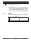
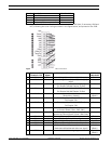
MIC612 cameras can use the following power supply units: MIC-240PSU-2 (230 VAC), MIC-
115PSU-2 (115 VAC), or MIC-240PSU-2 (24 VAC). The dimensions (H x W x D) of the PSU
enclosures are: 90 x 260 x 160 mm (3.54 x 10.24 x 6.3 in.). The weight is 3.2 kg (7.1 lb).
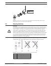
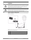
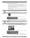
WARNING!
If the camera is mounted ball down, it is essential that the connector and base area of the
camera are completely sealed from water ingress. Any water getting into the connector is
liable to cause corrosion to the connector pins, leading to unreliable operation of the camera
unit.
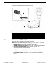
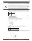
WARNING!
To prevent water from penetrating the composite cable connector threads, the 25 mm thread
should be sealed at final installation using PTFE tape (not supplied). Alternatively, a suitable
sealant may be liberally applied to the thread prior to final tightening.