


MIC612 Thermal Camera Installation | en 17
Bosch Security Systems, Inc. Installation Manual F.01U.249.416 | 2.0 | 2012.09
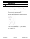
4 Installation
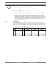
4.1 Typical Installation Configurations
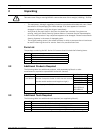
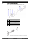
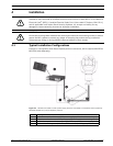
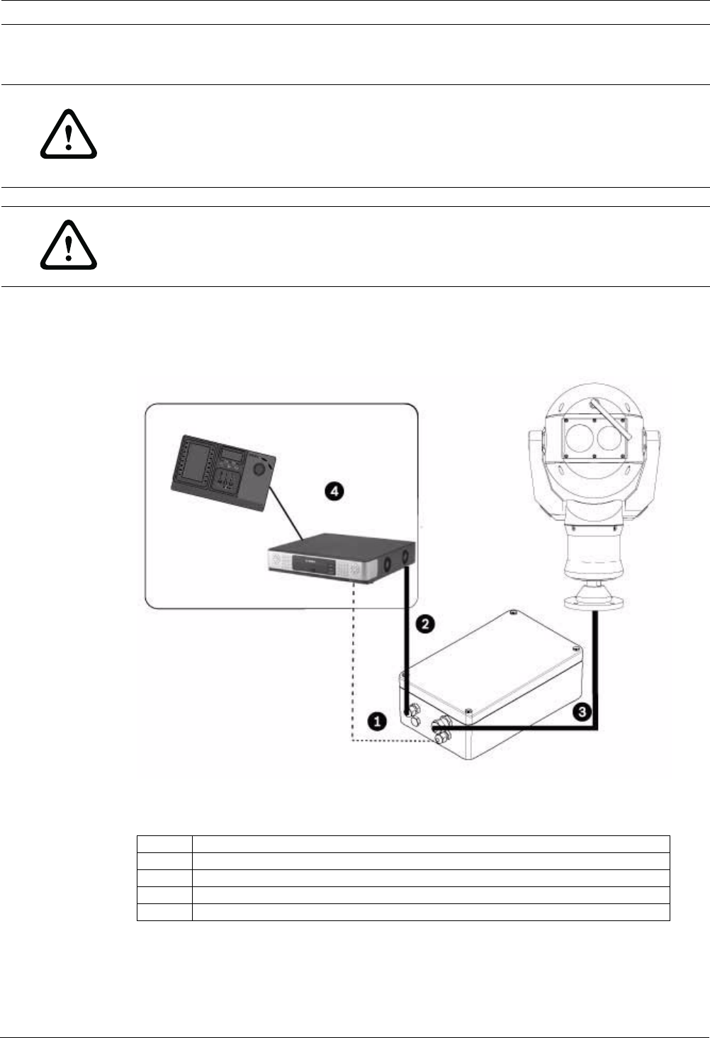
Example 1: Configuration with Bosch Biphase protocol connection, which requires MIC-BP3or
MIC-BP4 (sold separately).
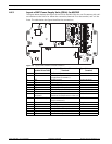
Figure 4.1 MIC612 connected to a MIC power supply, which is connected to a head-end control system by
Shielded Twisted Pair (STP) for Biphase protocol.
CAUTION!
Installation must be made by qualified personnel and conform to ANSI/NFPA 70 (the National
Electrical Code
®
(NEC)), Canadian Electrical Code, Part I (also called CE Code or CSA C22.1),
and all applicable local codes. Bosch Security Systems, Inc. accepts no liability for any
damages or losses caused by incorrect or improper installation.
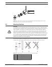
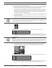
CAUTION!
Ensure that a strong tether between the camera pan shaft and the mounting surface is used to
secure the MIC camera to prevent any danger of dropping the product during installation.
Take extra care lifting or moving MIC612 cameras because of their weight.
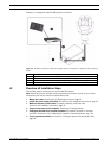
Number Description
1 Biphase connection between MIC power supply and head-end control system
2 Video connection between MIC power supply and head-end control system
3 Shielded composite cable between MIC camera and MIC power supply
4 Head-end control system (with Divar 700 or similar) with appropriate links