


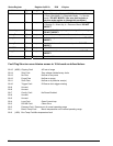
72 Instruction 3015-4275
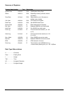
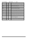
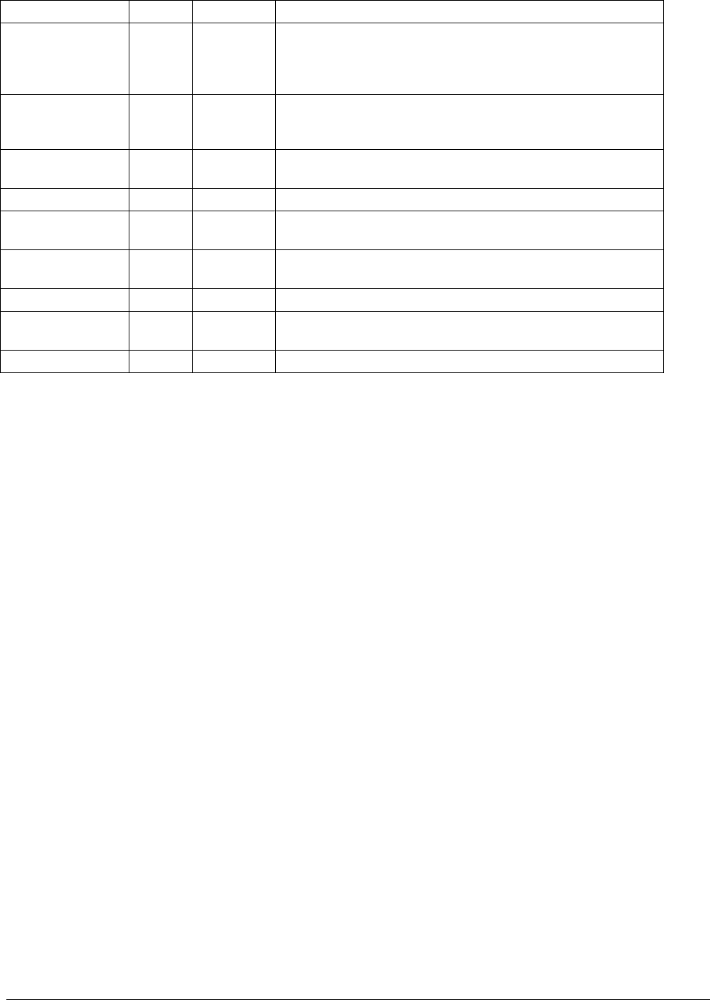
Status Register Register 0x0011h R/W 10 bytes
Variable Type Length Description
Mode UC 1 byte Defines Operating Mode of AGM300. 0 = normal Mode; 1
= Zone_Hold Mode; 2 = Diagnostic Mode; 3 = Service
mode. DO NOT MODIFY (use zone hold register or
service mode register to change this parameter)
State UC 1 byte Defines AGM300 Current State. 0 = Idle; 1 = Sampling; 2
= Zeroing; 3 = Warm Up, 4 = Pressure Check DO NOT
MODIFY
Measuring UC 1 byte Value = 1 if unit is acquiring detector signal for running avg.
DO NOT MODIFY
Active_Zone UC 1 byte Current Zone being checked. 0=zone1, 1=zone2, etc.
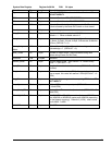
Max _Alarm UC 1 byte Indicates highest non-acknowledged alarm level DO NOT
MODIFY
Alarm_Count UC 1 byte Number of alarms that are currently active DO NOT
MODIFY
UNUSED UC 1 byte UNUSED
Loop_Card UC 1 byte Value = 1 if 4-20mA card has been detected DO NOT
MODIFY
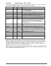
Fault UI 2 bytes See Note Below
Fault Flag Structure uses bitwise access to 16 bit word as defined below:
Bit 15 (MSB) Clipping Fault A/D out of range
Bit 14 Zero Fault Zero voltage outside factory limits
Bit 13 No Flow No flow on any zone
Bit 12 Purge Flow No flow on purge
Bit 11 Zone Flow No flow on a particular zone(s)
Bit 10 Trigger Fault IR Source clock trigger missing
Bit 9 Unused
Bit 8 Unused
Bit 7 Config. Fault No Zones Enabled
Bit 6 Unused
Bit 5 Unused
Bit 4 Loop Fault Open Current loop
Bit 3 RS-485 Fault Comm Error
Bit 2 Pressure Fault Pressure out of normal operating range
Bit 1 Bench Temp Fault Bench temperature out of normal operating range
Bit 0 (LSB) Box Temp Fault Box temperature fault