


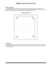
16 Instruction 3015-4275
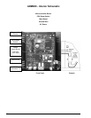
AGM300 - Current Loop Interfaces
Optional 4–20 mAdc Outputs
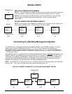
Upon installation of the optional 4–20 mAdc Interface Board (Page 7) (P/N 3015-3133), the AGM300 has the
capability of providing dual 4-20 mAdc scrolling current loop outputs for connection to external monitoring
devices.
The interfaces are set up as follows:
Loop 1 indicates zone area
Loop 2 indicates PPM
Connection
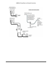
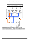
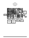
The external devices are connected to the AGM300 using a shielded dual twisted pair cable. Use any of the
remaining service knockouts to gain access to the interior of the monitor. Locate the Dual 4–20 mAdc Output
connector (Page
7) and remove it from the circuit board. Secure the wire leads to the connector orienting them
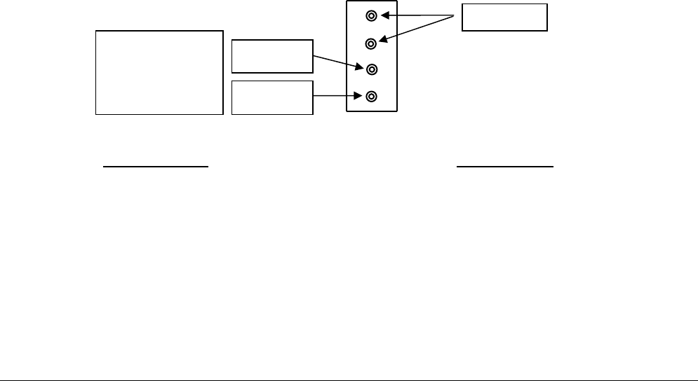
as shown in the diagram below. Check to make sure the polarity matches the wiring at the external device.
When you are through securing the connections, carefully plug the connector back onto the circuit board.
NOTE: When one or both current loop outputs are not used, install a jumper wire between the ground the
unused loop terminal(s) to prevent the system from generating a current loop fault.
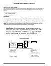
CAUTION - The loop outputs have isolated grounds.
Therefore, the cable shield should be terminated at the
receiver and not at the AGM300. The signal for both
current loops must be returned to the AGM300.
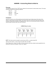
Current Loop Connector
NOTE: The ground connections are common.
LOOP 1 = ZONE
LOOP 2 = PPM
5 mAdc = Zone 1 Default
6 mAdc – Zone 2 0.016 mAdc = 1 PPM
--- Scalable via Software
--- 4 mAdc = 0 PPM
20 mAdc = Zone 16 20 mAdc = 1000 PPM
LOOP 2
PPM
LOOP 1
ZONE
NOTE:
SIGNAL OUT
ONLY DO NOT
APPLY POWER
GROUND