


Instruction 3015-4275 59
Working with the Diagnostic Screen
Overview
The Diagnostic Screen displays reference values for use by repair technicians for troubleshooting purposes.
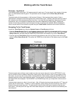
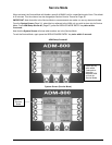
Navigating to the Diagnostic Screen
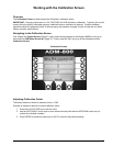
Display the System Screen (Page 31); press the key adjacent to the target AGM300 unit to go to that
monitor’s AGM Setup Screen #1 (Page
37); and then press the DIAG key to go to the selected monitor’s
Diagnostic Screen.
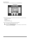
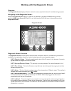
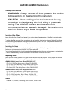
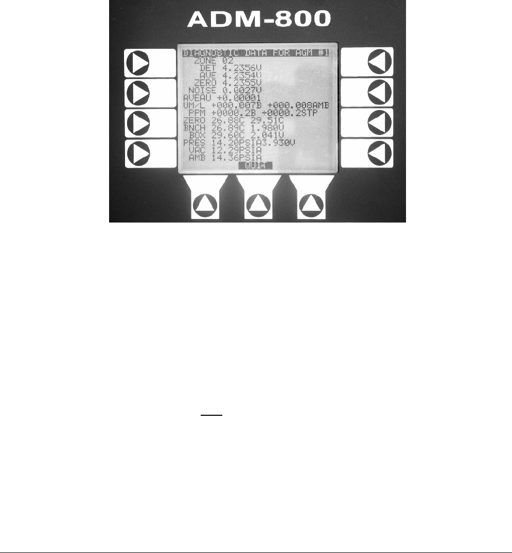
Diagnostic Screen
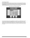
Diagnostic Screen Overview
The Diagnostic Screen contains sensor data and status information useful for troubleshooting various fault
conditions. An explanation of each line is given below along with normal operating ranges.
LINE 1: Detector Voltage – This is the peak-to-peak output of the IR sensor, in the absence of ammonia
gas this value can range from 3.900V to 4.500V.
LINE 2: Average Detector Voltage – This is simply a running average of the values displayed in line 1.
LINE 3: Zero Voltage – This is the IR sensor output that was stored during the last purge cycle and has
the same range as line 1.
LINE 4: Noise – This is a 16 point running average of the noise portion of IR bench output. This reading is
valuable mainly when ammonia gas is NOT
present.
LINE 5: Average Absorbency – This is the optical absorbency computed from the values in lines 2 and 3.
In the absence of ammonia gas the absorbency is 0.000AU. When sampling gas, its value varies
proportionally with the gas concentration.
LINE 6: uMoles/L – This is the absolute concentration in micro-moles per liter of ammonia gas based on
line 4 and the internal calibration. There are two figures given. The first (which is annotated by a B) is the
actual measurement at the IR bench. The second is the calculated value corrected to ambient conditions
(temperature + pressure).