


Instruction 3015-4275 v
Functional Overview
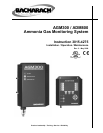
General Description
The AGM300 is designed to support compliance to federal, state and local safety codes governing ammonia
gas emissions. Avoiding significant ammonia gas loss reduces equipment replacement costs, maintains
equipment efficiency, promotes safety, and protects the environment.
The AGM300 provides for the continuous monitoring of ammonia gas levels in up to 16 separate test zones.
Each zone can be independently programmed to identify leak (small), spill (medium), or evacuation (large)
levels of gas. The instrument also retains a log of previous readings that can be easily accessed for analysis.
An audible alarm and large LED indicators are provided to signal alarm conditions, and relay contacts are
provided for the connection of external alarm devices. The system also includes two 4–20 mA current loop
interfaces (optional) for connection to external devices.
The AGM300 requires only minor periodic maintenance such as the occasional replacement of filters. The
instrument incorporates active diagnostics that continuously monitor the system for proper operation. An LED
indicator is provided to indicate system malfunctions, and fault codes are displayed that enable the operator to
identify the source of the fault.
Communication Options
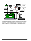
The AGM300 features full two-way communications via an RS-485 interface. MODBUS RTU is the
communication protocol standard. The instrument can be connected directly to a Building Management System
or it may be operated as a stand-alone system using the ADM800 Ammonia Display Module.
An RS-232C port is also provided for connection to a PC. This enables the AGM300 to be setup from a
personal computer.
Please refer to the Appendix for a more complete discussion of communication protocols.
Suggested Location of Sampling Points
At the point of an ammonia gas leak the gas is nearly pure. As the gas is dispersed into the air, the gas
molecules diffuse causing a dilution of the original concentration. The AGM300 measures the ammonia gas
concentration at the precise point the sample is collected. Therefore, if the termination of the collection line is
not at the exact point of the gas leak, then the unit will read a diluted mixture of the gas and air.
It should also be noted that when ammonia gas is cold it is heaver than air and settles below the leak point, but
as the gas warms to room temperature it becomes lighter than air and tends to collect above the point of a leak.
Consequently, sampling points should ideally be located as close as possible to the source of potential leaks. If
this is impractical, then the alarm set points should be adjusted for that zone to compensate for the dilution of
the gas. DO NOT plug any of the zones. Plugging a zone will give the monitor a false indication during
start up.
The AGM300 should be centrally located in the mechanical room and be readily accessible for easy visual
monitoring and servicing. Air sample tubing may be run in lengths up to 500 feet. The fresh air purge line
should draw from an area that does not contain any ammonia gas and cannot exceed 300 feet in length. The
exhaust line should run to an out side location if possible. The length of the exhaust line cannot exceed
300 feet.
Ideally, two to three pick up points spaced around each chiller will provide sufficient coverage. It may be
necessary to perform a “smoke” test of the mechanical room to determine the best locations. The smoke test
would provide the pattern of air currents present in the mechanical room.