Instruction 3015-4275 11
Changing Terminator Settings
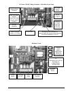
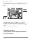
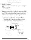
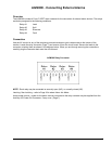
The terminator switch is shipped from the factory in the terminated or “IN” position. This is the correct setting if
the AGM300 is connected as a single device, or it is the last device on the network chain. If the AGM300 is
being installed in the middle of a network, the terminator must be moved to the “OUT” position.
Locate the switch and determine its position. If it needs to be moved, slide the switch to the appropriate
position.
Node Address DIP Switch Settings
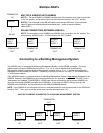
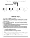
(Refer to Multiple AGM's and Connecting to a Building Management System)
Each AGM300 on the network must have a distinct node address. The node address may be set from 1 to 15.
Four dip switches numbered 1, 2, 4, 8 on the main circuit board are used to define this value by setting the
correct combination of dip switches to their ON positions. The node address is the sum of the switch numbers
that are ON.
Example: - For node address “5” switches 1 and 4 are ON.
- For node address “13” switches 1, 4, & 8 are ON.
Power must be cycled to elect this change.
Personal Computer
(Refer to AGM300 PC Software Section)
The AGM300 may be connected to a personal computer using the RS-232 interface on the left side of the
enclosure.
Software will be provided upon request or as a download from:
http://www.bacharach-inc.com/downloads.htm.
Network Node
Address
Switch
Terminator
Switch
IN OUT


