


Instruction 3015-4275 55
CRITICAL FAULTS
• NO FLOW ON ZONE – Go to the System Screen (Page
47) and press the ZONES key. The Zone
Screen (Page
44) will display a “NO FLOW” message in each individual zone affected. Check for a
blockage in the air sample line or at the line end filter. Once the blockage has been cleared, the
AGM300 will return to normal operation after the zone has been sampled. NOTE: This can take some
several minutes since it is dependent upon how many zones there are and their lengths. The AGM300
will clear the fault the next time it polls the effected zone and the ADM800 will return to normal
operation the next time that it polls the AGM300.
• NO FLOW ON PURGE – Check the purge line for a blockage. Verify that the length of the purge line
and exhaust line do not exceed 300 feet in length.
• NO FLOW DETECTED – Check for proper pump operation. Check the water trap – drain if necessary.
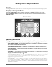
• CLIPPING FAULT – The detector voltage may be out of tolerance. Check the Diagnostic Screen
(Page
59) for the DET voltage, AVE voltage and ZERO voltage. Call the factory with this information for
further instructions.
• REZERO VOLT TOL – The detector output voltage is out of tolerance. Check the Diagnostic Screen
as in item 4 and contact the factory for assistance.
• TRIGGER FAULT – No trigger from IR source pulser. Contact factory with all information from the
Diagnostic Screen for further instructions.
NON CRITICAL FAULTS
• BOX TEMP FAULT – Enclosure’s internal temperature is outside normal range (or IR sensor has
failed). Check the installation to verify that the monitor is not being subjected to extreme temperatures.
Verify that the ventilation holes are not obstructed. Check the Diagnostic Screen for the ZERO
temperature, BNCH temperature and BOX temperature. Call the factory with this information for further
instructions.
• BENCH TEMP FAULT – Optical bench is outside of normal operating range (or sensor has failed).
Check the installation to verify that the monitor is not being subjected to extreme temperatures. Check
the Diagnostic Screen for the ZERO temperature, BNCH temperature and BOX temperature. Call the
factory with this information for further instructions.
• PRESSURE SENSOR – Manifold pressure is outside normal operating range (or sensor has failed).
Check the Diagnostic Screen and record ALL data. Call the factory with this information for further
instructions.
• LOOP FAULT – This would only be displayed if the dual 4–20 mA option was installed and one or both
current loops are open. Check the wiring to load/monitoring circuit on both 4–20 mA loops.
• CONFIG FAULT – There is an error in AGM Setup Screen #2 – Number Zones Installed field, or in
ADM Setup Screen #1 – Number of AGMS on Network field. Check that the number of zones installed
for each AGM unit and the number of AGM units on the network are properly programmed. Check to
ensure that the manifold solenoid cable connector in each AGM unit is securely fastened to its terminal
connector. Check for an illegal parameter. If necessary, reset to the factory default settings.
Reset to Factory Default Settings
IMPORTANT: Performing this function wipes out all program parameters, alarms, faults, trends and
log files.
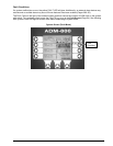
Resetting the AGM300
– Press and hold down the Factory Default switch inside the AGM300 (Page 7);
cycle the AC power OFF and then ON; listen for five beeps; and then release the switch. Reprogram the
AGM300 per Section AGM300 – Setup Programming on Page
37.
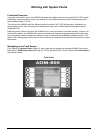
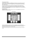
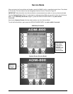
Resetting the ADM800
– Occasionally it will be necessary to rest the ADM800 to factory default settings.
From the System Screen (Page
31), press and hold the key adjacent to the ALARMS function; cycle AC
power OFF and then ON; listen for five beeps; and then release the key.