


YORK INTERNATIONAL 9
FORM 160.49-O2
To Display CHILLED LIQUID TEMPERATURES:
Press CHILLED LIQUID TEMPS display key as de-
scribed on page 7 to produce the following alphanu-
meric display message:
CHILLED LEAVING = XXX.X°F, RETURN = XXX.X°F
To Display REFRIGERANT PRESSURE:
Use REFRIGERANT PRESSURE display key as
described on page 7 to produce the following alpha-
numeric display message:
EVAP = XXX.X PSIG; COND = XXX.X PSIG
To Display OIL PRESSURE:
Use OIL PRESSURE display key as described on
page 7 to produce the following alphanumeric dis-
play message:
OIL PRESSURE = XXXX.X PSID
The differential pressure displayed is the pressure dif-
ference between the high side oil pressure transducer
(output of oil filter) and the low side oil pressure trans-
ducer (compressor housing). Displayed value includes
offset pressure derived from auto-zeroing during
“START SEQUENCE INITIATED”. If either transducer
is out-of-range, XX.X is displayed. Oil pressure is
calculated as follows:
______ PSID = (HOP – LP) – OFFSET PRESSURE
OFFSET PRESSURE: Pressure differential between
the HOP transducer and LOP transducer outputs dur-
ing a 3 second period beginning 10 seconds after the
start of “START SEQUENCE INITIATED”. During this
time, the transducers will be sensing the same pres-
sure and their outputs should indicate the same pres-
sure. However, due to accuracy tolerances in trans-
ducer design, differences can exist. Therefore, to com-
pensate for differences between transducers and as-
sure differential pressure sensing accuracy, the OFF-
SET PRESSURE is subtracted algebraically from the
differential pressure. The offset pressure calculation
will not be performed if either transducer is out-of-range.
The offset value will be taken as 0 PSI in this instance.
To Display OPTIONS:
This key is not used.
NO OPTIONS INSTALLED
is displayed when this key is pressed.
To Display SSS MOTOR CURRENT / VOLTS:
(Solid State Starter Applications Only)
If chiller is equipped with a YORK Solid State Starter,
use SSS MOTOR CURRENT / VOLTS key to dis-
play 3-phase compressor motor current and 3-phase
Solid State Starter input line voltage.
Continuously pressing this key will display the mo-
tor current and line voltage alternately. When used
with the DISPLAY HOLD key, motor current and
line voltage will alternately be displayed each time
this key is pressed. The messages are as follows:
A AMPS = XXXX; B AMPS = XXXX; C AMPS = XXXX
V A-B = XXXX; V B-C = XXXX; V C-A = XXXX
If chiller is not equipped with a Solid State Starter,
this key produces the following message:
SOLID STATE STARTER NOT INSTALLED
In PROGRAM mode, this key is used to display the
applicable line voltage range (200-208VAC, 220-
240VAC, 380VAC, 400VAC, 415VAC, 440-480VAC,
500-600VAC, Supply Voltage Range Disabled). The
correct line voltage range is programmed at the
YORK factory and is checked by the service tech-
nician at start-up. For security reasons, a special
access code is required to program the line volt-
age range. The line voltage range is used to deter-
mine a low line voltage threshold for cycling shut-
down. Refer to “System Setpoints” for Trip/Reset
values.
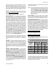
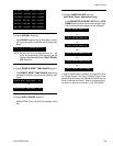
DISPLAY
READS
CONDENSER PRESS. = < 6.8 PSIG, or > 300 PSIG XX.X PSIG
EVAPORATOR PRESS. = < 50 PSIG, or > 125 PSIG XX.X PSIG
EVAP. PRESS. (BRINE) = < 25 PSIG, or > 100 PSIG XX.X PSIG
HOP TRANSDUCER = < 59.1 PSIG, or > 314.9 PSIG XX.X PSIG
LOP TRANSDUCER = < 23.2 PSIG, or > 271.8 PSIG XX.X PSIG
DISCHARGE TEMP. = < 20.3°F; > 226.4°F XXX.X°F
OIL TEMP. = < 20.3°F; > 226.4°F XXX.X°F
LEAVING CONDENSER
WATER TEMP.
= < 8.4°F; > 134.1°F XXX.X°F
ENTERING CONDENSER
WATER TEMP.
= < 8.4°F; > 134.1°F XXX.X°F
LEAVING EVAPORATOR = < 0°F XX.X°F
WATER TEMP. = > 81.1°F XX.X°F
ENTERING EVAPORATOR = < .1°F XX.X°F
WATER TEMP. = > 93°F XX.X°F
FIG. 4 – SYSTEM PARAMETERS – OUT OF
RANGE READINGS