


YORK INTERNATIONAL 11
FORM 160.49-O2
terms of minutes (to a maximum of 255). If not pro-
grammed, the default value is 100% FLA for 00 min-
utes. (See “Programming Systems Setpoints”, page 16.)
Thus, no pull down demand limit is imposed following
system start, and the % current limit setpoint is used.
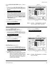
CLOCK – This key displays the day of the week, time of
day and calendar date. If not programmed, the default
value is
SUNDAY 12:00 AM 1/1/92 .
(See “Programming System Setpoints”, page 16.)
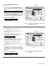
DAILY SCHEDULE – This key displays the programmed
daily start and stop times, from Sunday thru Saturday
plus Holiday. If desired, the Control Center can be pro-
grammed to automatically start and stop the chiller as
desired. This schedule will repeat on a 7-day calendar
basis. If the Daily Schedule is not programmed, the de-
fault value is 00:00 AM start and stop times for all days
of the week and the holiday. (Note that the system will
not automatically start and stop on a daily basis with
these default values because 00:00 is an “Impossible”
time for the Micro Board. See “Programming System
Setpoints”, page 17.) Finally, one or more days in the
week can be designated as a holiday (see description
under HOLIDAY setpoint) and the Control Center can
be programmed (usually Daily Schedule setpoint) to
automatically start and stop the chiller on those days so
designated. The operator can override the time clock
at any time using the COMPRESSOR switch.
Note that if only a start time is entered for a particular
day, the compressor will not automatically stop until a
scheduled stop time is encountered on a subsequent
day.
HOLIDAY – This key indicates which days in the upcom-
ing week are holidays. On those designated days, the
chiller will automatically start and stop via the holiday
start and stop times programmed in the DAILY SCHED-
ULE setpoint. It will do this one time only and the follow-
ing week will revert to the normal daily schedule for that
day.
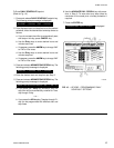
REMOTE / RESET TEMP RANGE – This key displays
the maximum offset of remote LCWT setpoint reset. This
offset is either 10° or 20°F as programmed. When in the
REMOTE mode, this value is added to the operator pro-
grammed CHILLED LIQUID TEMP setpoint and the sum
equals the temperature range in which the LCWT can
be reset. For example, if the operator programmed
CHILLED LIQUID TEMP setpoint is programmed with a
value of 10°F, then the CHILLED LIQUID TEMP setpoint
can be remotely reset over a range of 46°F to 56°F (46
+ 10 = 56). If not programmed, the default value for this
parameter is 20°F.
For additional information on remote LCWT reset, refer
to Form 160.49-PW13.
NOTE: If an Energy Management System is interfaced
to the Control Center for the purpose of remote
LCWT setpoint reset, then the operator pro-
grammed REMOTE RESET TEMP RANGE
value determines the maximum value of tem-
perature reset controlled by the Energy Man-
agement System.
DATE LOGGER – This key is used when an optional
printer is connected to the MicroComputer Control Cen-
ter. Refer to Form 160.49-N7 for operation instructions.
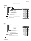
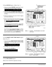
SSS MOTOR CURRENT/VOLTS – This key is used on
Solid State Starter applications only. Although this is a
display key, it is used to program the applicable AC
power line voltage range (380VAC, 400VAC, 415VAC,
440-480VAC, 550-600VAC). The MicroComputer Con-
trol Center uses this entry to determine the under-volt-
age and overvoltage shutdown threshold. For each
line voltage category, there is an undervoltage and ov-
ervoltage shutdown threshold. If the AC power line volt-
age exceeds these thresholds for 20 continuous sec-
onds, the chiller shuts down and displays
MON 10:00 AM LOW LINE VOLTAGE
– or –
MON 10:00 AM HIGH LINE VOLTAGE
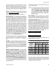
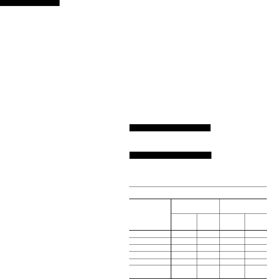
This overvoltage and undervoltage protection can be
disabled. Refer to chart below:
For security reasons, a special access code is required
to program the supply voltage range. The supply voltage
range is programmed at the factory and should only be
changed by a service technician.
LOW / HIGH LINE VOLTAGE TRIP / RESET VALUES
COMPRESSOR
LOW LINE VOLTAGE HIGH LINE VOLTAGE
MOTOR
OPERATING POINT OPERATING POINT
SUPPLY VOLTAGE
CUTOUT-(V) CUTIN-(V) CUTOUT-(V) CUTIN-(V)
RANGE – (V)
(
ON FALL) (ON RISE) (ON RISE) (ON FALL)
380 305 331 415 414
400 320 349 436 435
415 335 362 454 453
440-480 370 400 524 523
550-600 460 502 655 654
Supply Voltage
NONE 0 NONE 0
Range Disabled