


YORK INTERNATIONAL 29
FORM 160.49-O2
IMPORTANT!!!: Although this message is generally
indicative of a defective proximity probe, it is possible
that the compressor has been damaged. If the high
speed thrust bearing is not inspected by a qualified
service technician prior to starting the chiller, further
severe compressor damage could result. The chiller
cannot be restarted until the “Special Reset Proce-
dure” in YORK Service manual, Form 160.49-M3 is per-
formed by a qualified service technician.
MON XX:XX AM – HIGH SPEED DRAIN TEMP
The chiller has shut down because the “Proximity/Tem-
perature Sensor” has detected the temperature of the
high speed drain line has reached 250.0°F or greater.
IMPORTANT: If the chiller has shut down displaying
this message, it cannot be restarted until a qualified
service technician performs visual inspection of the
high speed thrust bearing and performs a special reset
procedure. This special reset procedure is detailed in
YORK Service manual, Form 160.49-M3. Failure to
perform the visual inspection prior to restarting the
chiller could result in severe compressor damage!!!
MON XX:XX AM – OPEN DRAIN TEMP THERMOCOUPLE
The chiller is shut down because the “Proximity/Tem-
perature Sensor” thermocouple or high speed drain tem-
perature wiring between the “Proximity/Temperature
Sensor” module and the MicroComputer Control Cen-
ter has been disconnected or has a poor electrical con-
nection.
IMPORTANT: Open thermocouple shutdowns would
typically indicate hardware or wiring defects and should
not result in any damage to the compressor high speed
thrust bearing. Therefore, a bearing inspection is not
required. However, due to the critical nature of these
circuits, anytime this shutdown occurs, a special re-
set procedure must be performed by a qualified ser-
vice technician before the chiller can be restarted.
This procedure is detailed in Service manual, Form
160.49-M3.
MON XX:XX AM – DC UNDERVOLTAGE
The “Proximity/Temperature Sensor” module becomes
unstable in operation when the +24VDC supply de-
creases to +17VDC. Therefore, the Micro Board moni-
tors the +24VDC supply and when it decreases to
+19VDC, it shuts down the chiller and displays this
message, preventing invalid “Proximity Sensor Safety”
or “High Speed Drain Temp” safety shutdowns. The
chiller will automatically restart when the voltage in-
creases to greater than +19.7 VDC.
MON XX:XX AM – AUX SAFETY SHUTDOWN
The system is shut down because an external device,
connected to digital input board TB1-31 (Auxiliary Safety
Shutdown Input), has initiated a system shutdown. This
input is a general purpose input that can be used to
annunciate a user-defined safety shutdown. To restart
chiller, press COMPRESSOR switch to STOP-RESET
position and then to START position.
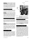
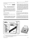
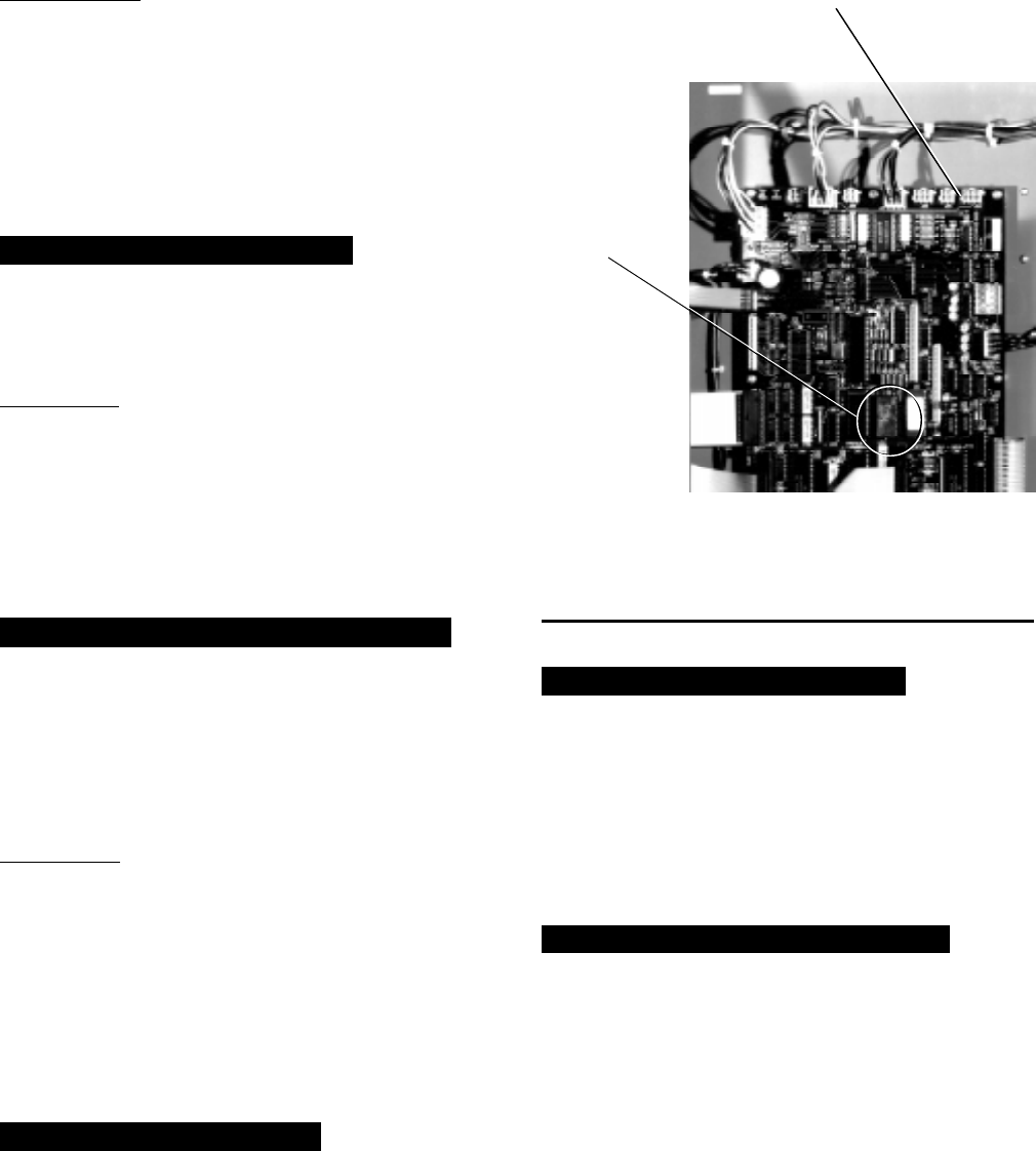
REPLACE RTC. U16 – REPROGRAM SETPOINTS
Indicates that the battery located inside the REAL-
TIME CLOCK IC chip (U16 on the Micro Board) is
defective. This battery provides back-up power to the
RTC memory (RAM) in the event of a utility AC power
failure. This assures the system setpoints will be main-
tained. If this message appears, the RTC IC chip (U16)
on the Micro Board must be replaced. If there had been
a power failure while this message is displayed, the
setpoints will have been lost and must be repro-
grammed. Order a replacement RTC IC chip (YORK
part number 031-00955-000) from the YORK Parts Dis-
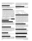
tribution Center. With AC power removed from system,
locate RTC chip U16 on the Micro Board and remove
existing RTC chip from socket and discard. Observe
anti-static precautions and install new RTC chip in
socket. Assure proper IC orientation – orientation notch
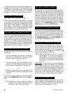
must be UP. (Refer to Fig. 14.)
FIG. 14 – MICROCOMPUTER CONTROL CENTER
LOCATION OF REAL TIME CLOCK U16
RTC IC CHIP
24673A
MICRO BOARD
U16 RTC
IC CHIP
REAL
TIME
CLOCK