


40 YORK INTERNATIONAL
oil pump sooner, depress the MANUAL OIL PUMP key
again.
On shutdown of the system for any reason, the oil pump
operates and continues to run for 150 seconds. The
system cannot restart during that time interval.
OIL HEATER
During long idle periods, the oil in the compressor oil
reservoir tends to absorb as much refrigerant as it can
hold, depending upon the temperature of the oil and
the pressure in the reservoir. As the oil temperature is
lowered, the amount of refrigerant absorbed will be in-
creased. If the quantity of refrigerant in the oil becomes
excessive, violent oil foaming will result as the pres-
sure within the system is lowered on starting. This foam-
ing is caused by refrigerant boiling out of the oil as the
pressure is lowered. If this foam reaches the oil pump
suction, the bearing oil pressure will fluctuate with pos-
sible temporary loss of lubrication, causing the oil pres-
sure safety cutout to actuate and stop the system. See
“Control Center, Section 2”.
To maintain the lowest possible concentration of re-
frigerant in the oil, the compressor oil reservoir is
equipped with a 115 volt electric reservoir oil heater.
The oil heater is thermostatically controlled at all times
during compressor shutdown to maintain the sump oil
at 145°F to 155°F. If the oil temperature falls below
55°F, the display will read
SYSTEM SHUTDOWN – PRESS STATUS
.
Pressing the STATUS key causes the message to read
DAY 10:00 AM – LOW OIL TEMP – AUTO START
. The system
will be allowed to automatically restart when oil tem-
perature rises to 30°F above condenser temperature.
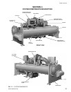
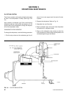
MOTOR DRIVELINE
The compressor motor is an open-drip-proof, squirrel
cage, induction type constructed to YORK design speci-
fications. 60 hertz motors operate at 3570 rpm. 50 hertz
motors operate at 2975 rpm.
(For 60 hertz motors 1750 HP and smaller; and 50
hertz motors 1400 HP and smaller) . . . the open motor
is provided with a D-flange, factory mounted to a cast
iron adapter mounted on the compressor.
(For 2000 HP 60 hertz motors; and 50 hertz motors
above 1400 HP) . . . a separate structural steel base is
furnished to provide rigid mounting of the compressor
and motor, independent of the evaporator shell, to en-
sure controlled alignment of the assembly. Motor is
mounted with final alignment at start-up.
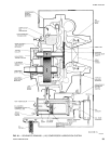
Motor drive shaft is directly connected to the com-
pressor shaft with a flexible disc coupling. Coupling
has all metal construction with no wearing parts to
assure long life, and no lubrication requirements to pro-
vide low maintenance.
For units utilizing remote electro-mechanical starters,
a terminal box is provided for field connected conduit.
Motor terminals are brought through the motor casing
into the terminal box. Jumpers are furnished for three-
lead type of starting. Motor terminal lugs are not fur-
nished. Overload/overcurrent transformers are fur-
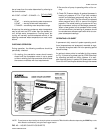
nished with all units. For units furnished with factory
packaged Solid State Starters, (optional) see right.
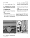
HEAT EXCHANGERS
Evaporator and condenser shells are fabricated from
rolled carbon steel plates with fusion welded seams.
Heat exchanger tubes are internally enhanced type.
The evaporator is a shell and tube, flooded type heat
exchanger. A distributor trough provides uniform distri-
bution of refrigerant over the entire shell length. Alumi-
num mesh eliminators are located above the tube bundle
to prevent liquid refrigerant carryover into the com-
pressor. Two 1-1/2" liquid level sight glasses are lo-
cated on the side of the shell to aid in determining
proper refrigerant charge. The evaporator shell con-
tains a dual refrigerant relief valve.
The condenser is a shell and tube type, with a dis-
charge gas baffle to prevent direct high velocity im-
pingement on the tubes. A separate subcooler is lo-
cated in the condenser.
The removable compact water boxes are fabricated of
steel. The design working pressure is 150 psig and the
boxes are tested at 225 psig. Integral steel water baffles
provide the required pass arrangements. Stub-out wa-
ter nozzle connections with Victaulic grooves are
welded to the water boxes. These nozzle connections
are suitable for Victaulic couplings, welding or flanges,
and are capped for shipment. Plugged 3/4" drain and
vent connections are provided in each water box.
REFRIGERANT FLOW CONTROL
Refrigerant flow to the evaporator is controlled by a
single fixed-orifice (or variable orifice).
Chillers can be provided with a REFRIGERANT LEVEL
CONTROL (EPROM version C.02.F(T).13 or later sup-
ports this feature). A level sensor senses the refriger-
ant level in the condenser and outputs an analog volt-