


YORK INTERNATIONAL 51
FORM 160.49-O2
VACUUM DEHYDRATION
To obtain a sufficiently dry system, the following in-
structions have been assembled to provide an effec-
tive method for evacuating and dehydrating a system
in the field. Although there are several methods of de-
hydrating a system, we are recommending the follow-
ing, as it produces one of the best results, and affords
a means of obtaining accurate readings as to the ex-
tent of dehydration.
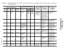
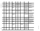
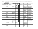
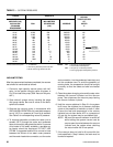
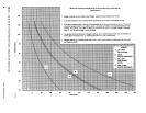
The equipment required to follow this method of dehy-
dration consists of a wet bulb indicator or vacuum
gauge, a chart showing the relation between dew point
temperature and pressure in inches of mercury
(vacuum), (see Table 3) and a vacuum pump capable
of pumping a suitable vacuum on the system.
OPERATION
Dehydration of a refrigerant system can be obtained
by this method because the water present in the sys-
tem reacts much as a refrigerant would. By pulling down
the pressure in the system to a point where its satura-
tion temperature is considerably below that of room
temperature, heat will flow from the room through the
walls of the system and vaporize the water, allowing a
large percentage of it to be removed by the vacuum
pump. The length of time necessary for the dehydra-
tion of a system is dependent on the size or volume of
the system, the capacity and efficiency of the vacuum
pump, the room temperature and the quantity of water
present in the system. By the use of the vacuum indi-
cator as suggested, the test tube will be evacuated to
the same pressure as the system, and the distilled
water will be maintained at the same saturation tem-
perature as any free water in the system, and this tem-
perature can be observed on the thermometer.
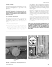
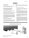
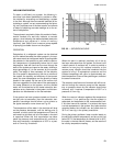
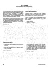
If the system has been pressure tested and found to
be tight prior to evacuation, then the saturation tem-
perature recordings should follow a curve similar to
the typical saturation curve shown as Fig. 22.
The temperature of the water in the test tube will drop
as the pressure decreases, until the boiling point is
reached, at which point the temperature will level off
and remain at this level until all of the water in the shell
is vaporized. When this final vaporization has taken
place the pressure and temperature will continue to
drop until eventually a temperature of 35°F or a pres-
sure of 5 mm Hg. is reached.
When this point is reached, practically all of the air
has been evacuated from the system, but there is still
a small amount of moisture left. In order to provide a
medium for carrying this residual moisture to the
vacuum pump, nitrogen should be introduced into the
system to bring it to atmospheric pressure and the
indicator temperature will return to approximately am-
bient temperature. Close off the system again, and start
the second evacuation.
The relatively small amount of moisture left will be car-
ried out through the vacuum pump and the tempera-
ture or pressure shown by the indicator should drop
uniformly until it reaches a temperature of 35°F or a
pressure of 5 mm Hg.
When the vacuum indicator registers this temperature
or pressure, it is a positive sign that the system is
evacuated and dehydrated to the recommended limit.
If this level cannot be reached, it is evident that there
is a leak somewhere in the system. Any leaks must be
corrected before the indicator can be pulled down to
35°F or 5 mm Hg. in the primary evacuation.
During the primary pulldown, keep a careful watch on
the wet bulb indicator temperature, and do not let it fall
below 35°F. If the temperature is allowed to fall to 32°F,
the water in the test tube will freeze, and the result will
be a faulty temperature reading.
FIG. 22 – SATURATION CURVE
LD00474