


30 YORK INTERNATIONAL
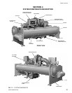
SECTION 3
SYSTEM OPERATING PROCEDURES
WARNING
OIL HEATERS
If the oil heater is de-energized during a shut-
down period, they must be energized for 12 hours
prior to starting compressor, or remove all oil and
recharge compressor with new oil. (See “Charg-
ing Unit With Oil”, page 43.)
NOTE: The oil heater is thermostatically controlled
and remains energized as long as the
fused disconnect switch to the starter or
turbo-modulator is energized.
CHECKING THE OIL LEVEL IN THE OIL
RESERVOIR
Proper operating oil level – the middle of the up-
per sight glass.
If the oil is excessively high after start-up, the
excess oil may be drained from the oil filter drain
valve while the compressor is running.
If oil level is low, oil should be added to the com-
pressor. (See “Charging Unit With Oil”, page 43.)
START-UP PROCEDURE
PRE-STARTING
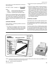
Prior to starting the chiller, observe the MicroCom-
puter Control Center. Make sure the display reads
SYSTEM READY TO START
.
To pre-start the chiller, use the following procedure:
1. Oil Heater – The oil heater must be energized for
12 hours prior to starting the chiller. The unit will
not start if the oil is less than 71°F. If not possible
the compressor oil should be drained and new oil
must be charged into the oil sump. (See “Charging
Unit With Oil”, page 43.)
2. Oil Pump – To check, press and release the
MANUAL OIL PUMP key under Service on the
Control Center. The oil pump will run for 10 min-
utes and shut down. Press and release the
MANUAL OIL PUMP key to stop the operation of
the oil pump for less than 10 minutes of operation.
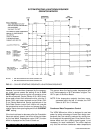
3. Pre-Rotation Vanes – To perform this test the
starter interlock terminals 3 and 4 must be
jumpered to allow vanes to open (remove the
jumper after test). Make sure the Control Center
is in the SERVICE mode, then press the prerotation
vanes OPEN and CLOSE keys to observe the
operation of the prerotation vanes. The Control
Center supplies a signal to operate the prerotation
vanes. The movement of the vanes will be dis-
played on the Control Center. The display readout
is active whenever power is supplied to the Con-
trol Center. Return from the SERVICE mode to
LOCAL, PROGRAM, or REMOTE mode to suit
the method of operation selected for the chiller
application. Refer to “Section 2”.
4. % Current Limit – Press the % CURRENT LIMIT
setpoint key on the Control Center. The “Display”
should read
CURRENT LIMIT = 100% FLA
on (Solid
State Starter units only, the display is
CURRENT LIMIT = 100% FLA, MTR CUR = XXXX FLA
)
if the Control Center was not programmed. If the
setpoint is not 100% and was predetermined for
the job application the Control Center should be
programmed to that specification. To program, re-
fer to “Section 2”.
5. All Control Center setpoints should be programmed
before the chiller is started. (Refer to “Section 2”.)
Prior to start, the clock must be programmed for
the proper day and time. Any setpoints which are
desired to be changed may be programmed. If not
programmed the “default” value setpoints are as
follows:
LCWT = 45°F
% Current Limit = 100% FLA
Pulldown Demand = None
Clock = Sun 12:00 A.M.
Daily Schedule = None
Holiday = None
Remote Reset Temp. Range = 20°F
Data Logger = No operation