


YORK INTERNATIONAL 23
FORM 160.49-O2
Therefore:
(100%) (50% x 200) = 100A = Vanes stop open-
ing
(104%) (50% x 200) = 104A = Vanes driven to-
ward close position.
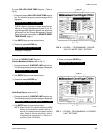
SYSTEM RUN – AUTO VANES
Displayed when the chiller is running, the MicroCom-
puter Control Center is in SERVICE mode, and the
vanes are operating in AUTO mode.
SYSTEM RUN – VANES OPENING
Displayed when the chiller is running, the MicroCom-
puter Control Center is in SERVICE mode with:
• The vanes operating in AUTO mode and opening to
maintain the leaving chilled water temperature
setpoint.
– or –
• The operator has pressed the vanes OPEN key on
the keypad.
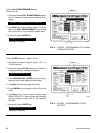
SYSTEM RUN – VANES CLOSING
Displayed when the chiller is running, the MicroCom-
puter Control Center is in SERVICE mode with:
• The vanes operating in AUTO mode and closing to
maintain the leaving chilled water temperature
setpoint.
– or –
• The operator has pressed the vanes CLOSE key on
the keypad.
SYSTEM RUN - VANES HOLDING
Displayed when the chiller is running, the MicroCom-
puter Control Center is in SERVICE mode, and the
operator has pressed the vanes HOLD key.
SYS READY TO START – VANES OPENING
Displayed when the chiller is running and the operator
has pressed the vanes OPEN key on the keypad.
SYS READY TO START – VANES CLOSING
Displayed when the chiller is not running and the op-
erator has pressed the vanes CLOSE key on the key-
pad.
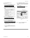
SYS READY TO START – VANES HOLDING
Displayed when the chiller is running and the operator
has pressed the vanes HOLD key on the keypad.
SYSTEM RUN – LEVEL VALVE OPENING
Displayed as a foreground message when manual re-
frigerant level control has been selected using the “Spe-
cial Setpoints Procedure” in Service manual, Form
160.49-M3 and operating in SERVICE mode. Indicates
an “OPEN” command is being output to the variable
orifice. Manual level control should be selected only by
a qualified service technician.
SYSTEM RUN – LEVEL VALVE CLOSING
Displayed as a foreground message when manual re-
frigerant level control has been selected using the “Spe-
cial Setpoints Procedure” in Service manual, Form
160.49-M3 and operating in SERVICE mode. Indicates
a “CLOSE” command is being output to the variable
orifice. Manual level control should be selected only by
a qualified service technician.
SYSTEM RUN – AUTO LEVEL CONTROL
Displayed as a foreground message when manual re-
frigerant level control has been selected using the “Spe-
cial Setpoints Procedure” in Service manual, Form
160.49-M3 and operating in SERVICE mode. Indicates
that neither a “CLOSE” nor “OPEN” command is being
output to the variable orifice but is in “AUTO” mode.
Manual level control should be selected only by a quali-
fied service technician.
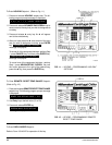
SYSTEM RUN – LOW PRESSURE LIMIT IN EFFECT
Displayed when the chiller is running and the evapora-
tor pressure falls to 56.2 PSIG (R-22); 27 PSIG (R-
134a). Simultaneously, the pre-rotation vanes will be
prevented from further opening. This action maintains
chiller operation to prevent low-evaporator-pressure
shutdown at 54.3 PSIG (R-22); 25 PSIG (R-134a).
When the evaporator pressure rises to 57.5 PSIG (R-
22); 28 PSIG (R-134a), the vanes will be permitted to
open. Low pressure limit feature is not used when pro-
gram jumper (JP3) is cut (Brine application).
SYSTEM RUN – HIGH PRESSURE LIMIT IN EFFECT
Displayed when the chiller is running and the condenser
pressure rises to 246.3 PSIG (R-22); 162.5 PSIG (R-
134a). Simultaneously, the pre-rotation vanes will be
inhibited from further opening. This action occurs to
prevent system shutdown on high condenser pressure