


20 YORK INTERNATIONAL
OTHER SERVICE KEYS
WARNING RESET – Press and release this key to re-
set any “WARNING” or “STATUS” message that can be
reset with this key, unless the condition still exists. To
reset any cycling or warning message, place the Con-
trol Center in SERVICE mode and press WARNING
RESET key. To reset any safety shutdown message,
press WARNING RESET key in SERVICE mode with
the COMPRESSOR switch in the STOP/RESET posi-
tion.
MANUAL OIL PUMP – This key is operational in any
mode. Press and release this key to run the oil pump.
Press and release the key again to stop the oil pump. A
10-minute maximum is imposed on the running of the oil
pump (i.e., the oil pump will automatically shut off after
10 minutes). If a longer running time is desired, the key
must be pressed again. The manual oil pump feature is
disabled during “START SEQUENCE INITIALIZED” to
allow for auto-zeroing of oil pressure transducers.
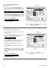
DISPLAY DATA – This key is operational in any three
of the Control Center modes of operation (SERVICE,
LOCAL or REMOTE). It is used to display certain sys-
tem operating parameters that are relevant to trouble-
shooting the chiller system.
Press and the DISPLAY DATA key. The following mes-
sages will sequentially scroll on the display. Each mes-
sage will be displayed for 2 seconds.
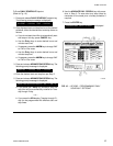
Messages 1 and 2 are only displayed if unit is equipped
with EPROM version C.02F(T).13 or later and Refriger-
ant Level Control has been enabled by a qualified ser-
vice technician using the “Special Setpoints and Pro-
gramming” procedures section of Service manual, Form
160.49-M3.
NO. 1
MANUAL VANE OPERATION ALLOWED
– Displayed when the
PRE-ROTATION VANES service keys have been se-
lected for manual VANE control. This allows these keys
to manually control the vanes in Service mode. The pro-
cedure to select manual vanes control is in Service
manual, Form 160.49-M3 and should be performed only
by a qualified service technician.
– or –
NO. 1
MANUAL LEVEL CONTROL ALLOWED
– Displayed when the
PRE-ROTATION VANES keys have been selected for
manual REFRIGERANT LEVEL control. This allows
these keys to manually control the refrigerant level con-
trol variable orifice in Service mode. When manual re-
frigerant level control is selected, the pre-rotation vanes
Service keys cannot be used to control the vanes. The
procedure to select manual refrigerant level control is in
Service manual, Form 160.49-M3 and should be per-
formed only by a qualified service technician.
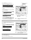
NO. 2
PULLDN LEVEL = XXX%; SETP = XXX%; ACTUAL = XXX%
– Displayed when there is a refrigerant level setpoint
pulldown (ramp) in effect. PULLDN LEVEL is the refrig-
erant level setpoint that is presently in effect. SETP is
the refrigerant level setpoint that has been programmed
by the service technician and ACTUAL is the refrigerant
level in the condenser. The pulldown period is 15 min-
utes in duration. During the pulldown period, a linearly
increasing ramp is applied to the level setpoint. This
causes the setpoint to increase from 0% to the pro-
grammed value over a period of 15 minutes. After the 15
minutes have elapsed, the setpoint remains the pro-
grammed value and this message is replaced by the
message
ACTUAL = XXX%; LEVEL SETP = XXX%
as
described below.
A refrigerant level setpoint pulldown is put into effect when
the vanes are driven from a fully closed to an open posi-
tion, if the actual refrigerant level is less than the level
setpoint when the vane motor end switch (VMS) opens.
If the actual level is greater than the setpoint when the
VMS opens, the level is controlled to the programmed
setpoint. Whenever the vanes go to the fully closed po-
sition (VMS closed), any pulldown that is in effect is can-
celled.
– or –
NO. 2
ACTUAL LEVEL = XXX%; LEVEL SETP = XXX%
– Displays
the actual refrigerant level in the condenser and the re-
frigerant level setpoint programmed by the service tech-
nician. This message replaces the previous message
after a refrigerant level setpoint pulldown period termi-
nates.
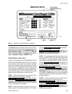
NO. 3
SAT TEMPS EVAP = XX.X°F; COND = XX.X°F
– This is the
refrigerant saturation temperatures for the evaporator and
condenser.
NO. 4
DISCHARGE TEMP = XXX.X°F; OIL TEMP = XXX.X°F
NO. 5
HOP = XX.X PSIG; LOP = XX.X PSIG
– This is the low oil
pressure (LOP) as measured at the oil sump and the
high oil pressure (HOP) as measured at the compres-
sor bearing input.