


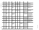
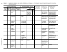


YORK INTERNATIONAL 49
FORM 160.49-O2
SECTION 7
MAINTENANCE
RENEWAL PARTS
For any required Renewal Parts, refer to “Parts Lists”
shown in “Reference Instructions”, page 2.
CHECKING SYSTEM FOR LEAKS
LEAK TESTING DURING OPERATION
The refrigerant side of the system is carefully pres-
sure tested and evacuated at the factory.
After the system is in operation under load, the high
pressure components should be carefully leak tested
with a leak detector to be sure all joints are tight.
If any leaks are indicated, they must be repaired im-
mediately. Usually, leaks can be stopped by tightening
flare nuts or flange bolts. However, if it is necessary to
repair a welded joint, the refrigerant charge must be
removed. (See “Handling Refrigerant for Dismantling
and Repair”, page 53.)
CONDUCTING R-22 PRESSURE TEST
With the R-22 charge removed and all known leaks
repaired, the system should be charged with a small
amount of R-22 mixed with dry nitrogen so that a ha-
lide torch or electronic leak detector can be used to
detect any leaks too small to be found by the soap
test.
To test with R-22, proceed as follows:
1. With no pressure in the system, charge R-22 gas
into the system through the charging valve to a
pressure of 2 psig.
2. Build up the system pressure with dry nitrogen to
approximately 10 psig. To be sure that the concen-
tration of refrigerant has reached all part of the sys-
tem, slightly open the oil charging valve and test
for the presence of refrigerant with a leak detector.
3. Test around each joint and factory weld. It is impor-
tant that this test be thoroughly and carefully done,
spending as much time as necessary and using a
good leak detector.
4. To check for refrigerant leaks in the cooler and con-
denser, open the vents in the cooler and condenser
heads and test for the presence of refrigerant. If no
refrigerant is present, the tubes and tube sheets
may be considered tight. If refrigerant is detected
at the vents, the heads must be removed, the leak
located (by means of soap test or leak detector)
and repaired.
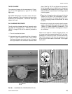
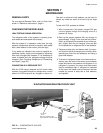
EVACUATION AND DEHYDRATION OF UNIT
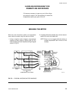
FIG. 21 – EVACUATION OF CHILLER
27385A(D)
LD00949