


YORK INTERNATIONAL 35
FORM 160.49-O2
4. Inspect and service electrical components as nec-
essary.
5. Perform chemical analysis of system.
NEED FOR MAINTENANCE OR SERVICE
If the system is malfunctioning in any manner or the
unit is stopped by one of the safety controls, consult
the “Operation Analysis Chart”, pages 47 through 48
of this instruction. After consulting this chart, if you
are unable to make the proper repairs or adjustments
to start the compressor or the particular trouble con-
tinues to hinder the performance of the unit, please
call the nearest YORK District Office. Failure to report
constant troubles could damage the unit and increase
the cost of repairs considerably.
NORMAL AND SAFETY SYSTEM SHUTDOWNS
Normal and safety system shutdowns have been built
into the chiller to protect it from damage during certain
operating conditions. Therefore, it should be understood
that at certain pressures and temperatures the sys-
tem will be stopped automatically by controls that re-
spond to high temperatures, low temperatures, and low
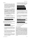
and high pressures, etc. Table 1 is an explanation of
each specific shutdown. If the chiller shuts down on a
“Safety” shutdown, the display will read
SYSTEM SHUTDOWN – PRESS STATUS
Upon pressing the STATUS key, the day-of-week, time-
of-day and cause of shutdown is displayed. Safety shut-
downs require the operator to manually reset the Con-
trol Center prior to restarting the chiller. When the dis-
play reads
START SEQUENCE INITIATED
, the cause of the
safety shutdown is automatically cleared from the
memory.
SAFETY SHUTDOWNS
• Power Failure (If auto restart programming jumper is
not installed on the Micro Board)
• Low Evaporator Pressure
• Low Oil Pressure
• High Condenser Pressure
• Evaporator Transducer or Probe Error
• High Discharge Temp
• High Oil Temp
• Oil Pressure Transducer
• Starter Malfunction Detected
• Faulty Discharge Temp Sensor
• Aux. Safety Shutdown
• Motor Phase Current Unbalance (Solid State Starter
Unit only)
• Proximity sensor
• Faulty Prox. Probe
• Open Drain Thermocouple
If the chiller shuts down on a “Cycling” shutdown the
display will read
SYSTEM SHUTDOWN – PRESS STATUS
.
Upon pressing the STATUS key, the day-of-week, time-
of-day and cause of shutdown are displayed. These
shutdowns do not require the operator to manually re-
set the Control Center prior to re-starting the chiller.
The chiller will automatically restart when the cycling
condition is removed.
CYCLING SHUTDOWNS
• Power Failure (If auto re-start programming jumper
is installed on the Micro Board)
• Low Water Temp
• Flow Switch
• System Cycling
• Multi-Unit Cycling
• Internal Clock
• Anti-Recycle
• Motor Controller (Manual reset of the CM-2 module
on E-M starter units; the logic board of the Solid
State Starter may be required)
• Power Fault
• Program Initiated Reset
• Low Oil Temp
• AC Undervoltage
• DC Undervoltage
• Low Line Voltage (Solid State Starter units only)
• High Line Voltage (Solid State Starter units only)
• Low Oil Temp. Differential
STOPPING THE SYSTEM (See Fig. 3, page 6)
The MicroComputer Control Center can be programmed
to start and stop automatically (maximum, once each
day) whenever desired. Refer to “Section 2”. To stop
the chiller, proceed as follows:
1. Push the COMPRESSOR STOP/RESET switch. The
Control Center display will show
SYSTEM COASTDOWN
for 150 seconds. If unit is
configured for a STEAM TURBINE application (pro-
gram jumper JP4 removed), this period is extended
to allow for a longer coastdown time. EPROM ver-
sion C.02F(T).11 provides a 6 minute coastdown