


10 YORK INTERNATIONAL
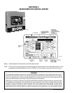
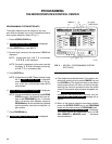
To Display CONDENSER LIQUID TEMPERATURES
(Field Installed Option Package):
Use CONDENSER LIQUID TEMPS display key as
described above to produce the following alphanu-
meric display message:
COND LEAVING = XXX.X°F; RETURN = XXX.X°F
NOTE: If the condenser liquid thermistors are not con-
nected, or both thermistors are “out of range”,
the display will blank when this key is pressed.
To Initiate a PRINT to Printer:
Press the PRINT key to initiate a printout to an op-
tional printer. When the key is pressed,
PRINT ENABLE
is displayed.
Refer to “MicroComputer Control Center – System
Status Printers” instruction, Form 160.49-N7 for de-
tails of the optional printers.
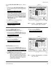
To Display MOTOR CURRENT:
Press the % MOTOR CURRENT display key as
described above to display motor current as a per-
cent of Full Load Amps (FLA). The message is as
follows:
MOTOR CURRENT = XXX% FLA
NOTE: • Liquid-Cooled Solid State Starter Applications
– the % Motor Current displayed is the highest
of three line currents divided by the programmed
chiller FLA value x 100%.
• Electro-Mechanical Starter Applications – the
% Motor Current displayed is the highest of the
three line currents.
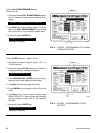
To Display OPERATING HOURS and STARTS
COUNTER:
Use the OPERATING HOURS key as described on
page 8, to produce the following message:
OPER. HOURS = XXXXX; START COUNTER = XXXXX
NOTE: The operating hours and starts counter can be
reset to zero. Refer to “Programming the Micro-
Computer Control Center”, page 14. However,
the purpose of the OPERATING HOURS key
is to display the total accumulated chiller run
time. Therefore, the operating hours should not
be arbitrarily reset.
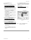
SYSTEM SETPOINTS
The system setpoints may be programmed by the sys-
tem operator. The Setpoints keys are located on the
Control Center keypad (see Fig. 3). To program, see “Pro-
gramming System Setpoints”, page 14. The following
is a description of these setpoints (with the English/
Metric jumper installed on the Micro Board):
CHILLED LIQUID TEMP – This key displays the leav-
ing chilled water temperature (LCWT) setpoint in degrees
Fahrenheit. If not programmed, the default value is 45°F.
See “Programming System Setpoints”, page 15).
NOTE: If an Energy Management System is interfaced
to the Control Center for the purpose of remote
LCWT setpoint reset, then the operator-pro-
grammed chilled liquid temperature will be the
base or lowest setpoint available to the Energy
Management System (EMS). This chilled liquid
temperature value must also be entered into the
EMS. Further, any subsequent change to this
value must also be entered into the EMS.
% CURRENT LIMIT – This key displays the maximum
value of motor current permitted by its programmed set-
ting. The value is in terms of percent of Full Load Amps
(FLA). If not programmed, the default value is 100%. (See
“Programming System Setpoints”, page 15.)
If chiller is equipped with a YORK Solid State Starter,
the system FLA is also displayed. This value is pro-
grammed by the factory and should never be changed.
The Micro Board uses this value to calculate and dis-
play the % motor current parameter that is displayed
when the % MOTOR CURRENT display key is pressed.
Also, proper current limit control depends on the cor-
rectly programmed FLA value. For security reasons, a
special access code is required to program the FLA value.
It should only be changed by a service technician.
PULL DOWN DEMAND – This function is used to pro-
vide energy savings following the chiller start-up. This
key displays a programmable motor current limit and a
programmable period of time. Operation is as follows:
Whenever the system starts, the Pull Down Demand
Limit is maintained for the programmed time, then the
current limit control returns to % current limit setpoint.
The maximum permitted motor current is in terms of %
FLA. The duration of time that the current is limited is in