


YORK INTERNATIONAL 7
FORM 160.49-O2
INTRODUCTION
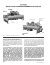
The YORK MicroComputer Control Center is a micro-
processor based control system for R-22 or R134a cen-
trifugal chillers. It controls the leaving chilled water tem-
perature via pre-rotation vane control and has the ability
to limit motor current via control of the pre-rotation vanes.
Further, it is compatible with YORK Solid State Starter
(optional), Variable Speed Drive (optional), and electro-
mechanical starter applications.
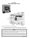
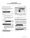
A keypad mounted on the front of the Control Center
(see Fig. 3) allows the operator to display system oper-
ating parameters on a 40 character alphanumeric dis-
play that is part of the keypad. These readings are dis-
played via “Display” keypad as follows: (In the English
mode; temperatures in °F, pressures in (PSIG) (in the
metric mode, temperatures in °C, Pressures in KPa).
If unit is equipped with EPROM version C.02F(T).12 or
later, the Control Center can be equipped with an op-
tional Chinese language display, either as a field retrofit
or factory supplied option on new units. This display
mounts on the control center door, directly above the
standard display. Both the standard and Chinese dis-
play will be present, providing display messages simul-
taneously in both English and Chinese language.
The Control Center must be configured for Chinese dis-
play by a qualified service technician. Instructions are
contained in YORK service manual, Form 160.49-M3.
• CHILLED LIQUID TEMPERATURES – LEAVING AND
RETURN
• REFRIGERANT PRESSURES – EVAPORATOR AND
CONDENSER
• DIFFERENTIAL OIL PRESSURE
• CONDENSER LIQUID TEMPERATURES – OPTIONAL
FIELD INSTALLED – LEAVING AND RETURN
• OPTIONS
• PRINT *
• HISTORY PRINT *
• MOTOR CURRENT IN % OF FULL LOAD AMPS
• SATURATION TEMPERATURES – EVAPORATOR AND
CONDENSER
• DISCHARGE TEMPERATURE
• OIL TEMPERATURE
• HIGH & LOW OIL PRESSURE TRANSDUCER PRES-
SURE
• SOLID STATE STARTER MOTOR CURRENT / VOLTS
(When Supplied)
• CONDENSER REFRIGERANT LEVEL
The system setpoints (see Fig. 3) are operator entered
on the front control center Setpoints keypad. These
setpoints can also be displayed on the 40 character al-
phanumeric display. The system setpoints are:
• CHILLED LIQUID TEMPERATURE (LCWT)
• % CURRENT LIMIT
• PULLDOWN DEMAND LIMIT
• CLOCK (TIME-OF-DAY)
• DAILY SCHEDULE (7 DAY TIME-CLOCK PROGRAM-
MING)
• HOLIDAY
• REMOTE RESET TEMPERATURE RANGE
• DATA LOGGER
• CONDENSER REFRIGERANT LEVEL
The cause of all system shutdowns (safety or cycling) is
preserved (until the system is reset or restarts) in the
microcomputer’s memory for subsequent viewing on the
keypad display. The operator is continually advised of
system operating conditions by various background and
warning messages. The keypad contains special ser-
vice keys for use by the service technician when per-
forming system troubleshooting.
The MicroComputer Control Center is designed to be
compatible with most Energy Management Systems
(EMS) in use today. The standard design allows for the
following EMS interface:
1. Remote Start
2. Remote Stop
3. Remote LCWT Setpoint (Pulse Width Modulated sig-
nal)
4. Remote Current Limit Setpoint (Pulse Width Modulated
signal)
5. A “Remote Mode Ready to Start” Status Contacts
6. Safety Shutdown Status Contacts
7. Cycling Shutdown Status Contacts
As an enhancement to the standard EMS features, an
optional card file with plug-in printed circuit boards is
available. These optional cards will accept a remote
LCWT 0 to 10°F or 0 to 20°F setpoint offset and/or re-
mote current limit setpoint interface from three user in-
put choices.
1. 4-20mA
2. 0-10VDC
3. Contact Closures
* These keys provide a print-out when the customer connects a com-
patible printer to the Micro Board RS-232 serial port. (See Form
160.49-N7.)