


8 YORK INTERNATIONAL
CONTROL CENTER
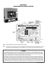
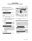
The Control Center front panel layout consists of five
key groups, one switch and a 1 line by 40 character al-
phanumeric vacuum fluorescent display: (see Fig. 3.)
CHARACTERISTIC DISPLAY – The alphanumeric
vacuum fluorescent display is located to the right of the
STATUS key. All messages, parameters, set points, and
data can be viewed at this location. The main communi-
cations between the operator or service technician and
the MicroComputer Control Center occurs on this dis-
play.
DISPLAY – Provide a direct readout of each monitored
parameter on the alphanumeric display.
ENTRY – These keys are used to enter the values for
the operator programmed setpoints. These keys are used
in conjunction with the Setpoint keys while in PRO-
GRAM mode.
SETPOINTS – These keys are used as follows:
1. To view each setpoint, in any mode, or
2. To select the individual setpoints that are programmed
by the operator in PROGRAM mode only.
Pressing the appropriate key enables the operator to
program that setpoint pressing the Entry keys.
SERVICE – Included in this group of keys are those func-
tions that are only relevant to servicing the chiller.
Typically, these keys would not be used for daily chiller
operation.
ACCESS CODE – Permits operator to access the pro-
gram.
PROGRAM – Permits operator to program the Control
Center.
MODE – Permits operator to check what mode the Con-
trol Center is presently in (LOCAL, REMOTE or SER-
VICE).
1. Service – allows manual PRV control with visual
display readout of PRV operation.
2. Local – allows manual compressor start from the
COMPRESSOR switch on the Control Center front.
3. Program – allows operator programming of system
setpoints.
4. Remote – allows remote start, remote stop of com-
pressor and remote reset of LCWT and % current
limit.
COMPRESSOR-START, RUN, STOP/RESET
SWITCH – This 3-position rocker switch is used to start
(except in REMOTE mode), stop/run/reset the system.
OPERATION
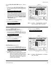
DISPLAYING SYSTEM PARAMETERS
The Display keys are used to display selected
monitored parameters as follows: (Refer to Fig. 3.)
• Press and release the appropriate Display key – the
message will be displayed for 2 seconds.
– or –
• Press and hold the appropriate Display key – the mes-
sage will be displayed and updated every 0.5 sec-
onds until the Display key is released.
– or –
• Press and release appropriate Display key, then press
and release the DISPLAY HOLD key – the message
will be displayed and updated every 2 seconds until
the DISPLAY HOLD key is again pressed and re-
leased, or 10 minutes have elapsed, whichever comes
first.
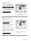
NOTE: If the display actually displays X’s, then the
monitored parameter is out of normal operat-
ing range (refer to Fig. 4). If the “English/Metric”
jumper is installed on the Micro Board, all tem-
peratures are displayed in degrees Fahrenheit
(°F) and all pressures are displayed in pounds
per sq. inch gauge (PSIG) except oil pressure
which is displayed in pounds per sq. inch differ-
ential (PSID). If the “English/Metric” jumper is
not installed, all temperatures are displayed in
degrees Centigrade (°C) and all pressures are
displayed in Kilo-Pascals (kPa).