


YORK INTERNATIONAL 31
FORM 160.49-O2
START-UP
1. If the chilled water pump is manually operated,
start the pump. The Control Center will not allow
the chiller to start unless chilled liquid flow is es-
tablished through the unit. (A field supplied chilled
water flow switch is required.) If the chilled liquid
pump is wired to the MicroComputer Control Cen-
ter the pump will automatically start, therefore,
this step is not necessary.
2. To start the chiller, press the COMPRESSOR
START switch. This switch will automatically spring
return to the RUN position. (If the unit was previ-
ously started, press the STOP/RESET side of the
COMPRESSOR switch and then press the START
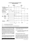
side of the switch to start the chiller.) When the
start switch is energized, the Control Center is
placed in an operating mode and any malfunction
will be noted by messages on the 40 character
alphanumeric display. (See Fig. 3.)
NOTE: Any malfunctions which occur during
STOP/RESET are also displayed.
When the chiller is shut down, the prerotation vanes
will close automatically to prevent loading the com-
pressor on start-up. When the prerotation vanes
are fully closed the “Display” will read
SYSTEM READY TO START – VANES CLOSED
when in SERVICE mode.
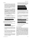
When the chiller starts to operate, the following auto-
matic sequences are initiated: (Refer to Fig. 15, “Chiller
Starting & Shutdown Sequence Chart”.)
1. The MicroComputer Control center alphanumeric
display message will read
START SEQUENCE INITIATED
for the first 50 seconds of the starting sequence,
(3 minutes if Micro Board JP6 removed).
2. The compressor vent line solenoid valve will open
after the first 5.83 minutes of operation. The sole-
noid will close automatically after the compressor
shuts down.
3. The 1R-1 contacts of the 1R start relay will re-
main open for the first 50 seconds of oil pump
operation. These contacts will close, starting the
compressor motor and the condenser water pump
at the end of the 50 second period.
4. The oil pump will start to circulate oil for a 50
second pre-run to establish oil flow and adequate
lubrication to all bearings, gears, and rotating sur-
faces within the compressor.
The high and low oil pressure transducers (OP)
and the oil temperature sensor (RT3) will sense
any malfunction in the lubrication system and ac-
tivate one of the following display messages:
DAY 10:30 AM – LOW OIL PRESSURE
DAY 10:30 AM – HIGH OIL TEMPERATURE
DAY 10:30 AM – LOW OIL TEMP – AUTOSTART
DAY 11:30 AM – OIL PRESSURE TRANSDUCER
5. The anti-recycle timer software function will oper-
ate after the 50 seconds of pre-run time. At this
time, the timer will be initiated and will run for 30
minutes after the compressor starts. If the chiller
shuts down during this period of time, it cannot be
started until the timer completes the 30 minute
cycle.
6. The chilled liquid pump contacts will close start-
ing the chilled liquid pump to allow liquid flow
through the cooler when the COMPRESSOR start
switch is energized.
7. After the first 50 seconds of operation, the com-
pressor will start and the Control Center display
message will read
SYSTEM RUN – CURRENT LIMIT IN EFFECT
while the
motor is accelerating to full speed. When the mo-
tor reaches full speed and the current falls below
100% FLA the message will read
SYSTEM RUN – LEAVING TEMP. CONTROL
8. For additional display messages and information
pertaining to the operation of the MicroComputer
Control Center, refer to “Section 2”.
9. Low Oil Temp. Differential.
CHILLER OPERATION
After the compressor reaches its operating speed, the
Prerotation Vanes will begin to open under the control
of the Microprocessor Board which senses the leaving
chilled liquid temperature. The unit capacity will vary
to maintain the leaving CHILLED LIQUID TEMPERA-
TURE setpoint. The Prerotation Vanes are modulated
by an actuator under the control of the Microprocessor
Board. The vane control routine employs proportional
plus derivative (rate) control action. A drop in chilled
liquid temperature will cause the actuator to close the
Prerotation Vanes to decrease chiller capacity. When
the chilled liquid temperature rises, the actuator will
open the Prerotation Vanes to increase the capacity of
the chiller.