


Getting Started Teledyne API – Model T300/T300M CO Analyzer
36
Included with your analyzer is a printed record (Final Test and Validation Data Sheet:
PN 04307; PN 04311) of the final performance characterization performed on your
instrument at the factory. This record is an important quality assurance and calibration
record for this instrument. It should be placed in the quality records file for this
instrument.
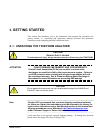
With no power to the unit, craefully remove the top cover of the analyzer and check for
internal shipping damage by carrying out the following steps:
1. Carefully remove the top cover of the analyzer and check for internal shipping
damage by:
Removing the setscrew located in the top, center of the Front panel;
Removing the two flat head, Phillips screws on the sides of the instrument (one
per side towards the rear);
Sliding the cover backwards until it clears the analyzer’s front bezel, and;
Lifting the cover straight up.
2. Inspect the interior of the instrument to make sure all circuit boards and other
components are in good shape and properly seated.
3. Check the connectors of the various internal wiring harnesses and pneumatic hoses
to make sure they are firmly and properly seated.
4. Verify that all of the optional hardware ordered with the unit has been installed.
These are listed on the paperwork accompanying the analyzer.
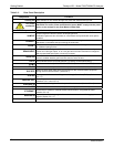
WARNING - ELECTRICAL SHOCK HAZARD
Never disconnect PCAs, wiring harnesses or electronic subassemblies
while instrument is under power.
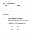
3.1.1. VENTILATION CLEARANCE
Whether the analyzer is set up on a bench or installed into an instrument rack, be sure to
leave sufficient ventilation clearance.
Table 3-1: Ventilation Clearance
AREA MINIMUM REQUIRED CLEARANCE
Back of the instrument
4 in.
Sides of the instrument
1 in.
Above and below the instrument
1 in.
Various rack mount kits are available for this analyzer. See Table 1-1 of this manual for
more information.
06864B DCN6314