


Communications Setup and Operation Teledyne API – Model T300/T300M CO Analyzer
148
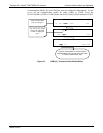
A Code-Activated Switch (CAS), can also be used on either port to connect typically
between 2 and 16 send/receive instruments (host computer(s) printers, data loggers,
analyzers, monitors, calibrators, etc.) into one communications hub. Contact Teledyne
API Sales for more information on CAS systems.
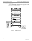
To assist in properly connecting the serial ports to either a computer or a modem, there
are activity indicators just above the RS-232 port. Once a cable is connected between
the analyzer and a computer or modem, both the red and green LEDs should be on.
If the lights are not lit, use small switch on the rear panel to switch it between DTE
and DCE modes.
If both LEDs are still not illuminated, make sure the cable properly constructed.
To configure the analyzer’s communication ports, use the SETUP>MORE>COMM
menu. Refer to Section 5.7.3 for initial setup.
6.4. RS-485 (OPTION)
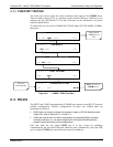
The COM2 port of the instrument’s rear panel is set up for RS-232 communication but
can be reconfigured for RS-485 communication. Contact Customer Service. If this
option was elected at the time of purchase, the rear panel was preconfigured at the
factory. Choosing this option disallows use of the USB port.
6.5. ETHERNET
When using the Ethernet interface, the analyzer can be connected to any standard
10BaseT or 100BaseT Ethernet network via low-cost network hubs, switches or routers.
The interface operates as a standard TCP/IP device on port 3000. This allows a remote
computer to connect through the network to the analyzer using APICOM, terminal
emulators or other programs.
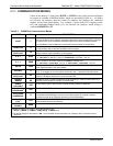
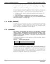
The Ethernet cable connector on the rear panel has two LEDs indicating the Ethernet’s
current operating status.
Table 6-2: Ethernet Status Indicators
LED FUNCTION
amber (link) On when connection to the LAN is valid.
green (activity Flickers during any activity on the LAN.
The analyzer is shipped with DHCP enabled by default. This allows the instrument to be
connected to a network or router with a DHCP server. The instrument will automatically
be assigned an IP address by the DHCP server (Section 6.5.2). This configuration is
useful for quickly
getting an instrument up and running on a network. However, for
permanent Ethernet connections, a static IP address should be used. Section 6.5.1 below
details how to configure the instrume
nt with a static IP address.
06864B DCN6314