


Teledyne API – Model T300/T300M CO Analyzer Troubleshooting and Service
279
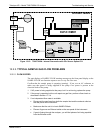
12.5.2. DC POWER SUPPLY
If you have determined that the analyzer’s AC mains power is working, but the unit is
still not operating properly, there may be a problem with one of the instrument’s
switching power supplies. The supplies can have two faults, namely no DC output, and
noisy output.
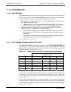
To assist tracing DC Power Supply problems, the wiring used to connect the various
printed circuit assemblies and DC Powered components and the associated test points on
the relay board follow a standard color-coding scheme as defined in the following table.
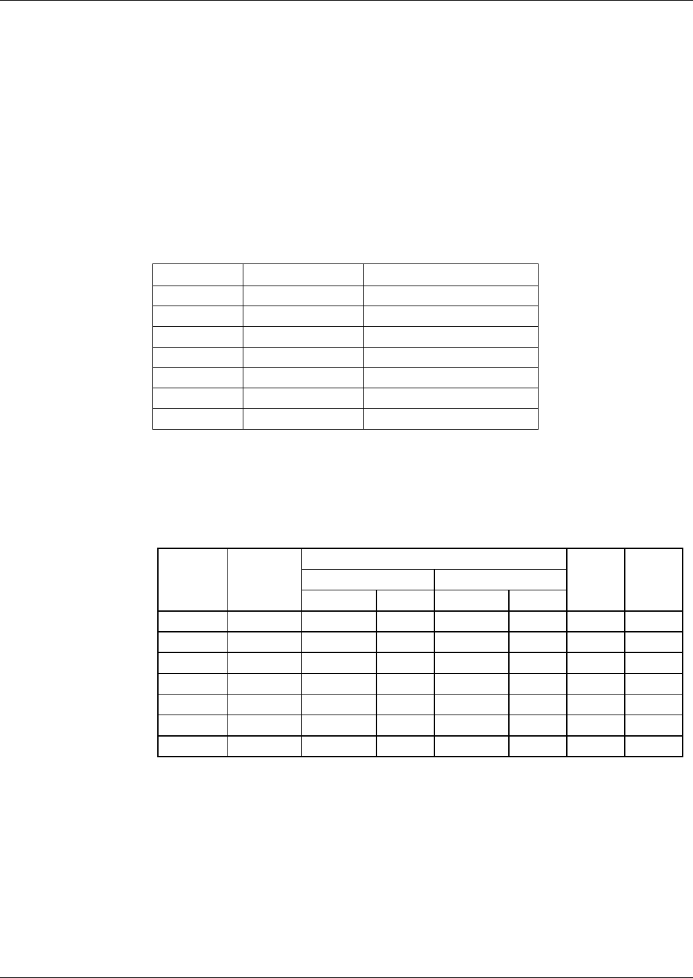
Table 12-6: DC Power Test Point and Wiring Color Codes
NAME TEST POINT# TP AND WIRE COLOR
Dgnd 1 Black
+5V 2 Red
Agnd 3 Green
+15V 4 Blue
-15V 5 Yellow
+12R 6 Purple
+12V 7 Orange
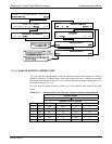
A voltmeter should be used to verify that the DC voltages are correct per the values in
the table below, and an oscilloscope, in AC mode, with band limiting turned on, can be
used to evaluate if the supplies are producing excessive noise (> 100 mV p-p).
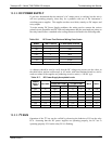
Table 12-7: DC Power Supply Acceptable Levels
CHECK RELAY BOARD TEST POINTS
FROM TEST POINT TO TEST POINT
POWER
SUPPLY
ASSY
VOLTAGE
NAME # NAME #
MIN V MAX V
PS1 +5 Dgnd 1 +5 2 4.8 5.25
PS1 +15 Agnd 3 +15 4 13.5 16V
PS1 -15 Agnd 3 -15V 5 -14V -16V
PS1 Agnd Agnd 3 Dgnd 1 -0.05 0.05
PS1 Chassis Dgnd 1 Chassis N/A -0.05 0.05
PS2 +12 +12V Ret 6 +12V 7 11.75 12.5
PS2 Dgnd +12V Ret 6 Dgnd 1 -0.05 0.05
12.5.3. I
2
C BUS
Operation of the I
2
C bus can be verified by observing the behavior of D1 on the relay
PCA. Assuming that the DC power supplies are operating properly, the I
2
C bus is
operating properly if D1 on the relay PCA is flashing.
06864B DCN6314