


Teledyne API – Model T300/T300M CO Analyzer Theory of Operation
317
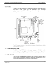
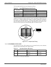
13.4.4.5. STATUS LEDS
Eight LEDs are located on the analyzer’s relay board to show the current status on the
various control functions performed by the relay board. They are listed on Table 13-4.
Table 13-4: Relay Board Status LEDs
LED COLOR FUNCTION STATUS WHEN LIT STATUS WHEN UNLIT
D1 RED Watch Dog Circuit
Cycles On/Off every 3 seconds under direct control of the analyzer’s
CPU.
D2 YELLOW Wheel Heater HEATING NOT HEATING
D3 YELLOW Bench Heater HEATING NOT HEATING
D4 YELLOW Spare N/A N/A
D5 GREEN
Sample/Cal Gas Valve
Option
Valve Open to CAL GAS FLOW Valve Open to SAMPLE Gas Flow
D6 GREEN Zero/Span Gas Valve Option Valve Open to SPAN GAS FLOW Valve Open to ZERO GAS FLOW
D7 GREEN Shutoff Valve Option Valve Open to CAL GAS FLOW
Valve CLOSED to CAL GAS
FLOW
D8 GREEN IR SOURCE Source ON Source OFF
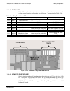
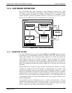
STATUS LED’s
DC VOLTAGE TEST
POINTS
RELAY PCA
PN 04135
Figure 13-15: Location of relay board Status LEDs
13.4.4.6. I2C WATCH DOG CIRCUITRY
Special circuitry on the relay board monitors the activity on the I
2
C bus and drives LED
D1. Should this LED ever stay ON or OFF for 30 seconds, the watch dog circuit will
automatically shut off all valves as well as turn off the IR Source and all heaters. The
GFC Wheel motor will still be running as will the Sample Pump, which is not controlled
by the relay board.
06864B DCN6314