


Troubleshooting and Service Teledyne API – Model T300/T300M CO Analyzer
292
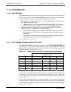
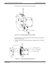
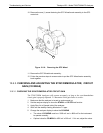
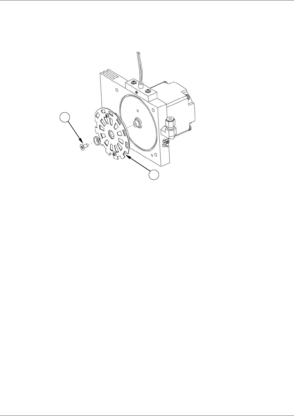
10. Remove the one (1) screw fastening the GFC Wheel/mask assembly to the GFC
motor hub.
11
12
Figure 12-18: Removing the GFC Wheel
11. Remove the GFC Wheel/mask assembly.
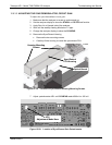
12. Follow the previous steps in reverse order to put the GFC Wheel/motor assembly
back together.
12.6.3. CHECKING AND ADJUSTING THE SYNC/DEMODULATOR, CIRCUIT
GAIN (CO MEAS)
12.6.3.1. CHECKING THE SYNC/DEMODULATOR CIRCUIT GAIN
The T300/T300M Analyzers will operate accurately as long as the sync/demodulator
circuit gain is properly adjusted. To determine if this gain factor is correct:
1. Make sure that the analyzer is turned on and warmed up.
2. Set the analyzer display to show the STABIL or CO STB test function.
3. Apply Zero Air to Sample Inlet of the analyzer.
4. Wait until the stability reading falls below 1.0 ppm.
5. Change the analyzer display to show the CO MEAS
The value of CO MEAS must be > 2800 mV and < 4800 mV for the instrument
to operate correctly.
Optimal value for CO MEAS is 4500 mV ± 300 mV. If it is not, adjust the value.
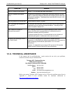
06864B DCN6314