


Troubleshooting and Service Teledyne API – Model T300/T300M CO Analyzer
286
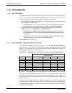
12.5.8.4. STATUS OUTPUTS
The procedure below can be used to test the Status outputs:
1. Connect a jumper between the “D“ pin and the “” pin on the status output
connector.
2. Connect a 1000 ohm resistor between the “+” pin and the pin for the status output
that is being tested.
3. Connect a voltmeter between the “” pin and the pin of the output being tested (see
table below).
Under the DIAG SIGNAL I/O menu (see Section 12.1.3), scroll through the inputs
and outputs until you get to the output in question. Alternately turn on and off the
output noting the voltage on the voltmeter, it should vary between 0 volts for ON and 5
volts for OFF.
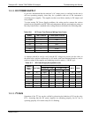
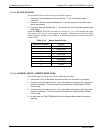
Table 12-12: Status Outputs Check
PIN (LEFT TO RIGHT) STATUS
1 SYSTEM OK
2 CONC VALID
3 HIGH RANGE
4 ZERO CAL
5 SPAN CAL
6 DIAG MODE
7 SPARE
8 SPARE
12.5.8.5. CONTROL INPUTS – REMOTE ZERO, SPAN
The control input bits can be tested by the following procedure:
1. Jumper the +5 pin on the Status connector to the U on the Control In connector.
2. Connect a second jumper from the
_
pin on the Status connector to the A pin on the
Control In connector. The instrument should switch from Sample Mode to ZERO
CAL R mode.
3. Connect a second jumper from the
_
pin on the Status connector to the B pin on the
Control In connector. The instrument should switch from Sample Mode to SPAN
CAL R mode.
4. In each case, the T300/T300M should return to Sample Mode when the jumper is
removed.
06864B DCN6314