


Teledyne API – Model T300/T300M CO Analyzer Troubleshooting and Service
277
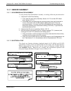
12.4.1.4. IR PHOTO-DETECTOR TEC TEMPERATURE
If the PHT DRIVE test parameter described in Table 11-3 is out of range there are four
possible causes of failure.
1. The screws retaining the IR photo detector to the absorption bench have become
loose.
Carefully tighten the screws, hand-tight and note whether, after the analyzer has
come up to operating temperature, whether the PHT DRIVE voltage has
returned to an acceptable level.
2. The two large transistor-type devices mounted to the side of the Absorption Bench
have come loose from the bench.
Tighten the retaining screws and note whether there is an improvement in the
PHT DRIVE voltage.
3. The photo-detector has failed. Contact the factory for instructions.
4. The sync demodulator circuit board has failed. Contact the factor for instructions.
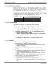
12.4.2. EXCESSIVE NOISE
Noise is continuously monitored in the TEST functions as the STABIL reading and
only becomes meaningful after sampling a constant gas concentration for at least 10
minutes. Compare the current STABIL reading with that recorded at the time of
manufacture (included in the T300/T300M
Final Test and Validation Data Sheet,P/N
04271 shipped with the unit from Teledyne API).
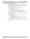
1. The most common cause of excessive noise is leaks. Leak check and flow check
the instrument described in Section 11.3.3 and 11.3.4.
2. Dete
ctor failure – caused by failure of the hermetic seal or over-temperature due to
poor heat sinking of the detector can to the optical bench.
In addition to increased noise due to poor signal-to-noise ratio, another indicator
of detector failure is a drop in the signal levels of the CO MEASURE signal and
CO REFERENCE signal.
3. Sync/Demod Board failure. There are many delicate, high impedance parts on this
board. Check the CO MEAS and CO REF Test Functions via the Front Panel
Display.
4. The detector cooler control circuit can fail for reasons similar to the detector itself
failing. Symptoms would be a change in MR RATIO Test Function when zero air is
being sampled.
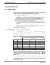
5. Also check the SIGNAL I/O parameter PHT DRIVE.
After warm-up, and at 25
o
C ambient, if PHT DRIVE < 4800 mV, the cooler is
working properly.
If PHT DRIVE is > 4800 mV there is a malfunction.
6. The +5 and 15 VDC voltages in the T300/T300M are provided by switching power
supplies.
06864B DCN6314