


Teledyne API – Model T300/T300M CO Analyzer Troubleshooting and Service
289
12.6. REPAIR PROCEDURES
This contains procedures that might need to be performed on rare occasions when a
major component of the analyzer requires repair or replacement.
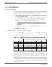
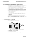
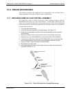
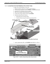
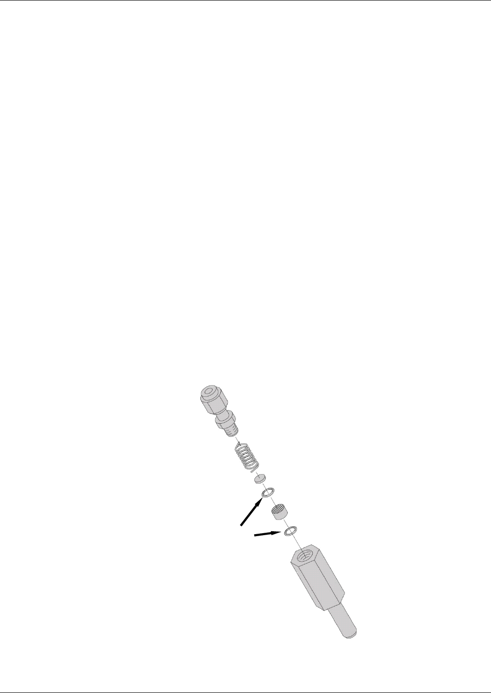
12.6.1. REPAIRING SAMPLE FLOW CONTROL ASSEMBLY
The critical flow orifice is housed in the flow control assembly (Teledyne API P/N
001760400) located on the top of the optical bench. A sintered filter protects the jewel
orifice so it is unusual for the orifice to need replacing, but if it does, or the filter needs
replacement please use the following procedure (see the Spare Parts list in Appendix B
for part numbers and kits):
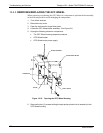
1. Turn off power to the analyzer.
2. Locate the assembly attached to the sample pump. See Figure 3-6.
3. Disco
nnect the pneumatic connection from the flow assembly and the assembly
from the pump.
4. Remove the fitting and the components as shown in the exploded view below.
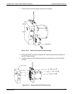
5. Replace the o-rings (P/N OR0000001) and the sintered filter (P/N FL0000001).
6. If replacing the critical flow orifice itself (P/N 000941000), make sure that the side
with the colored window (usually red) is facing upstream to the flow gas flow.
7. Apply new Teflon
®
tape to the male connector threads.
8. Re-assemble in reverse order.
9. After reconnecting the power and pneumatic lines, flow check the instrument as
described in Section 11.3.4.
Pneumatic Connector, Male 1/8”
(
P/N FT
_
70
Spring
(
P/N HW
_
20
)
Sintered Filter
(
P/N FL
_
01
)
Critical Flow Orifice
(P/N 00094100)
Make sure it is placed with the
jewel down)
O-Ring
(
P/N OR
_
01
)
Purge Housing
(
P/N 000850000
)
Figure 12-14: Critical Flow Restrictor Assembly/Disassembly
06864B DCN6314