


Troubleshooting and Service Teledyne API – Model T300/T300M CO Analyzer
280
12.5.4. TOUCHSCREEN INTERFACE
Verify the functioning of the touchscreen by observing the display when pressing a
touchscreen control button. Assuming that there are no wiring problems and that the DC
power supplies are operating properly, if pressing a control button on the display does
not change the display, any of the following may be the problem:
The touchscreen controller may be malfunctioning.
The internal USB bus may be malfunctioning.
You can verify this failure by logging on to the instrument using APICOM or a terminal
program to any of the communications ports. If the analyzer responds to remote
commands and the display changes accordingly, the touchscreen interface may be faulty.
12.5.5. LCD DISPLAY MODULE
Verify the functioning of the front panel display by observing it when power is applied
to the instrument. Assuming that there are no wiring problems and that the DC power
supplies are operating properly, the display screen should light and show the splash
screen with logo and other indications of its state as the CPU goes through its
initialization process.
12.5.6. RELAY BOARD
The relay board PCA (P/N 04135) can be most easily checked by observing the
condition of the its status LEDs on the relay board, as described in Section 12.1.4.3, and
the associated output when toggled on and
off through signal I/O function in the
diagnostic menu, see Section 12.1.3.
1. If the front panel display responds to button presses and D1 on the relay board is
NOT flashing then either the wiring between the touchscreen and the relay board is
bad, or the relay board is bad.
2. If D1 on the relay board is flashing and the status indicator for the output in question
(heater power, valve drive, etc.) toggles properly using the signal I/O function, then
the associated control device on the relay board is bad.
Several of the control devices are in sockets and can be easily replaced.
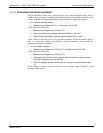
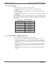
The table below lists the control device associated with a particular function:
Table 12-8: Relay Board Control Devices
FUNCTION
CONTROL
DEVICE
IN SOCKET
Wheel Heater K1 Yes
Bench Heater K2 Yes
Spare AC Control K3 Yes
IZS Valves U4 Yes
IR Source Drive U5 No
The IR source drive output can be verified by measuring the voltage at J16 with the IR
source disconnected. It should be 11.5± 0.5 VDC.
06864B DCN6314