


Theory of Operation Teledyne API – Model T300/T300M CO Analyzer
304
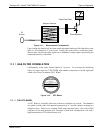
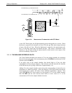
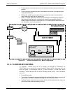
By placing the pump down stream from the sample chamber several problems are
avoided.
First the pumping process heats and compresses the sample air complicating the
measurement process.
Additionally, certain physical parts of the pump itself are made of materials that
might chemically react with the sample gas.
Finally, in certain applications where the concentration of the target gas might be
high enough to be hazardous, maintaining a negative gas pressure relative to
ambient means that should a minor leak occur, no sample gas will be pumped into
the atmosphere surrounding analyzer.
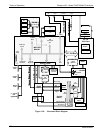
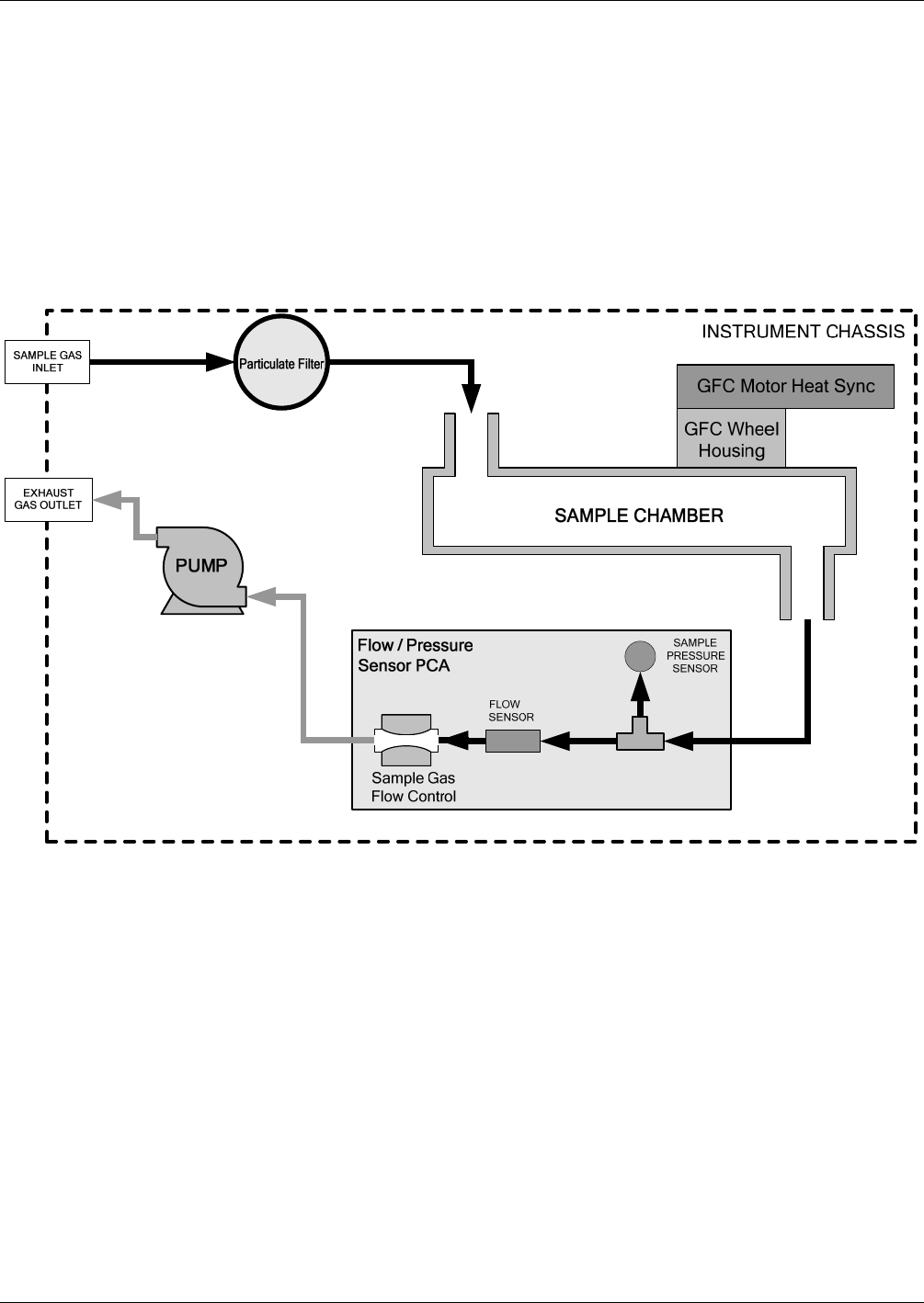
Figure 13-7: Internal Pneumatic Flow – Basic Configuration
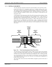
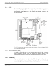
13.3. FLOW RATE CONTROL
To maintain a constant flow rate of the sample gas through the instrument, the
T300/T300M uses a special flow control assembly located in the exhaust gas line just
before the pump. In instruments with the O
2
sensor installed, a second flow control
assembly is located between the O
2
sensor assembly and the pump. These assemblies
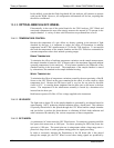
consist of:
A critical flow orifice.
Two o-rings: Located just before and after the critical flow orifice, the o-rings seal the
gap between the walls of assembly housing and the critical flow orifice.
A spring: Applies mechanical force needed to form the seal between the o-rings, the
critical flow orifice and the assembly housing.
06864B DCN6314