


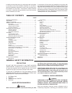
8
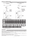
Refer to Table 2 for limitations of venting system design for
horizontal venting.
TABLE 2
GPV-540A-740A
Flue Outlet Dia. (Inches/mm) 9” (228.6)
Flue Reducer 9” x 8”
Dimensions -Supplied (Inches/mm) 228.6 x 203.2
Minimum Outlet Vent Dia. (Inches/mm) 8” (203.2)
Maximum Number 90° 4
Of Elbows 45° 8
Maximum Total Vent System 75
Length, Equiv. Feet/Meters (23 m)
When calculating the equivalent length of a venting system each
90° elbow is equivalent to 10 feet (3 m) of straight pipe. In no case
45° elbow is equivalent to 5 feet (1.5 m) of straight pipe. In no
case may the sum of the straight pipe lengths and the equivalent
length of the elbows exceeds 80 feet (24.3 m).
Note the minimum vent diameter in Table 2.
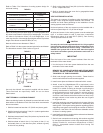
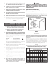
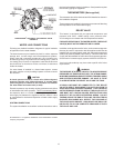
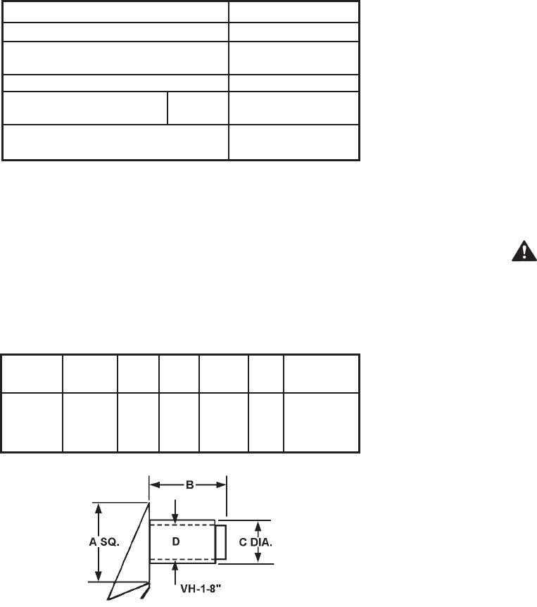
Refer to Table 3 for the correct vent terminal size for each heater.
The dimensions noted in Table 3 refer to Figure 5.
TABLE 3
Heater Terminal Rough-In
Model Model A B C D Dimensions
GPV
540A- VH-1-8” 19-7/8” 13” 10-9/16” 8-5/8” 11-1/16”
740A
FIGURE 5
Use only the sidewall vent terminal supplied with the heater.
These terminals are specifically listed for use on these
State heaters.
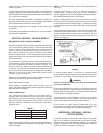
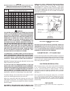
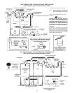
VENT TERMINAL LOCATIONS-EXHAUST
When considering location for sidewall vent terminals refer to the
latest edition of the National Fuel Gas Code which recommends
that vent terminals:
1. Shall be located not less than 12” (304.8 mm) above grade.
2. Shall be located not less than 7 feet (2.1 m) above grade when
adjacent to a public walkway.
3. Shall terminate at least 3 feet (0.9 m) above any forced air inlet
within 10 feet (3 m).
4. Shall terminate at least 4 feet (1.2 m) below, 4 feet (1.2 m)
horizontally from or 1 foot above any door, window or gravity
air inlet into any building.
5. Shall not be closer than 3 feet (0.9 m) from the inside corner
of an L- shaped structure.
6. Shall be located above the snow line in geographical areas
where snow accumulates.
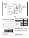
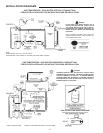
VENT SYSTEM INSTALLATION
This heater is a category III appliance when horizontally vented
through a wall using the supplied sidewall vent terminal. All
national and local codes pertaining to the installation of such
venting systems must be followed.
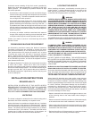
Horizontal portions of the vent system must be installed with a
minimum upward slope of 1/4” per foot of length.
All joints and seams in the venting system must be sealed gas
tight. If a silicone sealer is used, it must have a continuous
temperature rating of at least 500°F (260°C); Dow Corning
736 or equivalent must be used.
CAUTION
Use only the vent hood supplied with this kit. Only supplied
hood provides required clearances from combustibles, both
through the wall and the exterior siding. Termination of a
sidewall vent system with a device other than the supplied
vent hood could affect system performance and result in a
safety hazard.
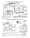
IMPORTANT
Plan the layout of the vent system backward from the vent
termination to the water heater.
1. Use the layout of the vent system backward from the vent
termination to the water heater.
BEWARE OF CONCEALED WIRING AND PIPING INSIDE
OF WALL. REFER TO TABLE 5 FOR THE MAXIMUM WALL
THICKNESS “B” FOR EACH MODEL.
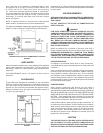
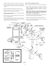
2. Slide hood through opening from outside. Fasten hood to
exterior wall with anchors and screws supplied.
3. Install covers plate and fasten to inside wall with 4 screws.
4. Attach a seal ring (Meltalbestos SR or equivalent) to the
vent hood collar, see Figure 7. Attach Selkirk Metalbestos
model PS or model G venting to the seal ring following the
venting manufacturer’s instructions. For total safety, it is
recommended that only venting listed for use with category
III appliances (positive vent pressure, non-condensing)
should be used between the heater and the vent hood, even
through national or local codes may allow the use of type B
or single-wall vent.
5. Install the remaining vent sections back to the heater, following
the venting manufacturer’s instructions on assembling and
sealing joints. Follow good venting practice regarding properly
supporting vent system and keeping the number of offsets to
a minimum. See Table 2 for the maximum allowable number
of elbows in venting system.
6. Install the ue reducer included with the exhaust hood between
the vent system and the heater.
7. Seal all vent connections and venting with sealants supplied
by vent pipe manufacturer or with a high-temperature silicone
sealant suitable for continuous temperatures of 500°F
(260°C). Acceptable sealant include Dow Corning 736
or equivalent.