


23
DANGER
THIS WATER HEATER IS EQUIPPED WITH AN ADJUSTABLE
THERMOSTAT TO CONTROL WATER TEMPERATURE. HOT
WATER TEMPERATURES REQUIRED FOR AUTOMATIC
DISHWASHER AND LAUNDRY USE CAN CAUSE SCALD BURNS
RESULTING IN SERIOUS PERSONAL INJURY AND/OR DEATH.
THE TEMPERATURE AT WHICH INJURY OCCURS VARIES WITH
THE PERSON’S AGE AND TIME OF EXPOSURE. THE SLOWER
RESPONSE TIME OF CHILDREN, AGED OR DISABLED PERSONS
INCREASES THE HAZARDS TO THEM. NEVER ALLOW SMALL
CHILDREN TO USE A HOT WATER TAP, OR TO DRAW THEIR
OWN BATH WATER. NEVER LEAVE A CHILD OR DISABLED
PERSON UNATTENDED IN A BATHTUB OR SHOWER.
THE WATER HEATER SHOULD BE LOCATED IN AN AREA
WHERE THE GENERAL PUBLIC DOES NOT HAVE ACCESS
TO SET TEMPERATURES.
SETTING THE WATER HEATER TEMPERATURE AT 120°F
(49°C) WILL REDUCE THE RISK OF SCALDS. Some states or
provinces require settings at specic lower temperatures.
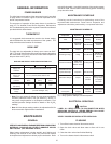
Below you will nd listed the approximate time-to-burn relationship
for normal adult skin. Short repeated heating cycles caused by
small hot water uses can cause temperatures at the point of use
to exceed the thermostat setting by up to 20F°. If you experience
this type of use, you should consider using lower temperature
settings to reduce scald hazards.
Temperature Time to Produce 2nd & 3rd
Setting Degree Burns on Adult Skin
180°F (82°C) Nearly instantaneous
170°F (77°C) Nearly instantaneous
160°F (71°C) About 1/2 second
150°F (66°C) About 1-1/2 seconds
140°F (60°C) Less than 5 seconds
130°F (54°C) About 30 seconds
120°F (49°C) More than 5 minutes
Valves for reducing point-of-use temperature by mixing cold and
hot water are available. Also available are inexpensive devices
that attach to faucets to limit hot water temperatures. Contact a
licensed plumber or the local plumbing authority.
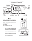
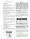
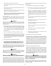
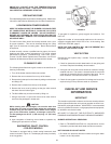
The water temperature is controlled by a thermostat, g. 2, which
has two sensing elements. One sensor is located near the top of
the tank and the other is near the center. The thermostat is set in
the lowest position before the heater leaves the factory.
The dial is adjustable and may be set for 120
0
(49°C)
to 180
0
F
(82°C) water temperature, but 120
0
F (49°C) is the recommended
starting point. It is suggested the dial be placed on the lowest
setting which produces an acceptable hot water supply. This will
always give the most energy efcient operation. The temperature
control has a 4F° xed differential.
ADJUSTMENT PROCEDURE (Initial Start-Up)
A minimum dynamic gas supply pressure of 8” w.c. for natural
gas is required before making any adjustment to the gas control
pressure regulator. Attempts to adjust the regulator during periods
of low gas supply pressure could result in overring of the heater
when the gas supply pressure returns to normal.
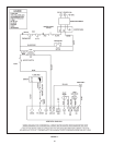
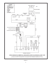
SEQUENCE OF OPERATION
– Power on.
– Heater in standby mode.
– Thermostat calls for heat.
– Blower motor starts.
– Blower operation closes the normally open blower prover/
blocked outlet safety pressure switch.
– On proof of airow, Honeywell S8680J ame control module
energized.
– 45 seconds prepurge cycle begins.
– Following prepurge cycle, the pilot gas valve is energized.
– At the same time, the electronic spark generator in the module
produces a high voltage spark pulse output.
– The voltage generates a spark at the ignitor that lights the
pilot.
– If the pilot does not light (or ame signal is less than 1 micro
A) within 15 seconds system locks out and must be reset by
turning burner switch “OFF” for a minimum of 1 minute. During
system lockout, blower still runs.
– When the pilot ame is established (ame is sensed by ame
rod), the main gas valve is energized.
– Main gas ows to main burner where it’s ignited by the pilot
ame. Now heater is in Heating Mode.
– During the Heating Mode:
If gas line pressure drops below the setting point, the ame
module is de-energized, gas valves closed, blower still runs.
If gas line pressure drops below the setting point then gas line
pressure increases to above the setpoint, heater starts again
from purging cycle.
If gas line pressure uctuates around the setpoint too quick
(less than a second) burner may still run with excessive gas
valve ON/OFF cycle you must turn off the unit immediately,
re-adjust the gas line regulator and/or install a larger gas
supply line!
If the blower inlet and/or intake hood, or ue outlet/hood is/are
blocked for any reason, the safety switches will open, which
will de-energize the ame control module.
– The spark generator is off.
– The ame module monitors pilot ame current. Should the
ame failure occur during the Heating Mode, the unit will start
again from purging cycle.
– Thermostat is satised, switch opens.
– Power is interrupted to the ame control module and blower
motor. Gas valves are closed.
– Heater is in Standby Mode.
– Thermostat is satised, switch opens.
– Power is interrupted to burner, turning off blower and ignition
control module. Solenoid and main gas valves are closed.
– Insufcient blower pressure causes safety pressure switches
to open.
WATER TEMPERATURE CONTROL