


24
1. Check gas line pressure with a manometer.
Set initial gas line pressure at 9-10” w.c. before turning the
heater “ON”.
Read gas line pressure and gas manifold pressure when the
heater main gas is “ON”.
Adjust gas line regulator setting if the gas line pressure drops
below 8” w.c. when heater main gas is “ON”.
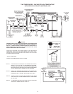
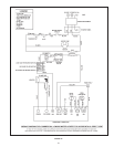
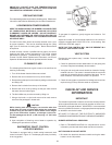
Check heater gas manifold pressure (see Table 10) using a
manometer connected to the manifold pressure tap on the
Robertshaw gas control valve, see Figure 10.
Important Note: Use gas manifold pressure as initial setup
only. The final air and gas settings should be based on fire
rate and flue gas 0
2
/C0
2
reading, see Table 10 for normal 0
2
/
C0
2
reading.
WARNING
Excessive gas line pressure drop and/or burner manifold
pressure too low may cause burner start/operate with
2. Cycle the burner “ON” and “OFF” several times to check
its operation. Make sure the gas line pressure is below
14” w.c. when burner is “OFF”. If gas line pressure exceeds
14” w.c. when the burner is off, the gas supply line size
must be increased to correct this problem (see Table 9 for
gas pipe size).
3. Check the operation of the limiting and operating controls.
4. Check the vent system seams and joints and ensure that there
is no discharge of ue products into the room. For standard
vertical vent systems, check the barometric damper control to
make sure it operates freely and there is no discharge of ue
products into the room.
5. Check the input rate by clocking the gas meter.
ADJUSTMENT PROCEDURE FOR FIRE-RATE,
LOW NOX AND HIGH ELEVATION (Fine-Tune)
An acceptable input rate is within 2% of the rated input for the
model. Should it be necessary to adjust the gas pressure to the
burner and/or air damper of the blower to obtain the full input rate,
these steps should be followed:
WARNING
Never set burner combustion too lean (causing noisy
operation) or too rich (causing combustion chamber
premature failure) see Table 10 for proper settings.
WARNING
Never set air damper outside of its adjustment range of the
Important Note: Final gas and air settings should be based on ue
gas CO
2
or O
2
reading (see Table 10). Increase burner manifold
pressure will increase re rate and ue gas CO
2
reading. Increase
air damper setting will decrease re rate and decrease ue
gas CO
2
reading. Adjustable air damper is preset for the rated
re-rate prior to delivery, should not be re-adjusted unless it’s
a high elevation application and/or a direct vent (long air intake
vent) application.
1. Fire Rate Adjustment (including direct vent installation).
a. Make sure the gas supply line pressure reads
8” w.c. (2 kPa) or higher when the heater is running.
b. R emove the pressure reg ulator cov er sc re w
(Figure 10) and adjust the pressure by tuning the
adjustment screw w/a small screwdriver clockwise to
increase gas pressure into the burner and re rate.
Counterclockwise to decrease gas pressure and input
rate.
c. Clock gas meter, repeat above Step (b) to achieve the
specic input rate.
d. Measure ue gas O
2
and/or CO
2
(see Table 10) for
acceptable O
2
/CO
2
range.
If the O
2
or CO
2
reading is within the acceptable range,
then proceed to Step (f).
If the O
2
or CO
2
reading is out of range, adjust air
damper is required.
e. Repeat Steps (b), (c), (d) if air damper is adjusted.
f. Cycle heater ON/OFF.
g. Replace the gas regulator cover, pressure tap and
tighten the damper center bolt.
2. Adjustment for Low NOx Emission Application.
The water heater is preset at factory for Low Nox emission
combustion. Due to the installation variations, fine-tune
adjustments may be required. To lower NOx emission level
(30PPM corrected at 3% O
2
or lower is required by SCAQMD),
air damper setting may need to be slightly increased. To
increase air damper setting, loosen the center nut of the
inlet air damper, rotate the damper clockwise slightly, then
tighten the center nut. After re-set the air damper, cycle heater
ON/OFF and check re-rate and ue gas CO
2
/O
2
reading.
3. Adjustment for High Elevation Application
Installation above 2000 feet sea level require new air damper
settings. All the nal settings should be based on ue gas
CO
2
/O
2
reading, see Table 10. To increase air damper setting,
loosen the center bolt of the inlet air damper, rotate the damper
clockwise slightly, then tighten the center bolt. After re-setting
the air damper, cycle heater ON/OFF and check re-rate and
ue gas CO
2
/O
2
reading.
WARNING
UNDER NO CIRCUMSTANCES SHOULD THE INPUT RATE
EXCEED THE INPUT RATE SHOWN IN THE HEATER RATING
PLATE. OVERFIRING COULD RESULT IN DAMAGE OR
SOOTING OF THE HEATER.
SHOULD OVERHEATING OCCUR OR THE GAS SUPPLY FAIL
TO SHUT OFF, TURN OFF THE MANUAL GAS CONTROL VALVE
TO THE APPLIANCE.