


19
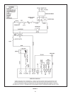
HEATER WIRING
IF ANY OF THE ORIGINAL WIRE AS SUPPLIED WITH THE
APPLIANCE MUST BE REPLACED, IT MUST BE REPLACED
WITH 105°C WIRE OR ITS EQUIVALENT, EXCEPT IN THE
BURNER HOUSING USE 200°C WIRE.
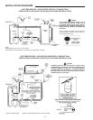
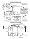
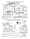
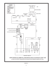
The power burner is wired to the heater as shown in Figure 11
for GPG models and Figure 12 for GPV models. The model
and rating plate provided the electrical information needed
to size the complete heater branch supply.
All electrical work must be installed in accordance with the
National Electrical Code and local requirements.
When installed, the appliance must be electrically grounded in
accordance with local codes or, in the absence of local codes,
with the National Electrical Code, ANSI/NFPA 70-1987.
DO NOT ENERGIZE THE BRANCH CIRCUIT BEFORE THE
HEATER TANK IS FILLED WITH WATER.
START UP
IMPORTANT
Factory Start-Up is required for activating warranty and assuring
maximum operating performance. Contact your local sales
representative or Autho-rized Start-Up Agent to arrange a FREE
Certied Start-Up.
If you have not already done so, contact your local State Sales
Representative or Authorized GPG/GPV Start-Up Agent and
set-up a date for the start-up service.
The time to ask any questions you may have about your unit is when
the State Authorized GPG/GPV Start-Up Agent is there. Please do
not hesitate to ask the agent any questions which you may have
regarding the units start-up, operation or maintenance.
CAUTION
BEFORE PROCEEDING WITH THE OPERATION OF THE
UNIT, MAKE SURE HEATER AND SYSTEM ARE FILLED
WITH WATER AND ALL AIR IS EXPELLED FROM HEATER
AND PIPING.
NEVER OPERATE THE HEATER WITHOUT FIRST BEING
CERTAIN IT IS FILLED WITH WATER AND A TEMPERATURE
AND PRESSURE RELIEF VALVE IS INSTALLED IN THE RELIEF
VALVE OPENING OF THE HEATER.
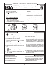
FILLING
1. Close the heater drain valve by turning handle clockwise.
2. Open a nearby hot water faucet to permit the air in the system
to escape.
3. Fully open the cold water inlet pipe valve allowing the heater
and piping to be lled.
4. Close the hot water faucet as water starts to ow.
5. The heater is ready to be operated.
PURGING
Gas line purging is required with new piping or systems in which
air has entered.
CAUTION
PURGING SHOULD BE PERFORMED BY PERSONS
EXPERIENCED IN THIS TYPE GAS SERVICE. TO AVOID RISK OR
FIRE OR EXPLOSION, PURGE DISCHARGE MUST NOT ENTER
CONFINED AREA OR SPACES WHERE IGNITION CAN OCCUR.
THE AREA MUST BE WELL VENTILATED AND ALL SOURCES
OF IGNITION MUST BE INACTIVATED OR REMOVED.
The following test equipment should be on hand: (all test
equipment must be acclimated to ambient temperature before
calibration and use.)
– CO
2
indicator (Fyrite or similar) or O
2
analyzer
– CO indicator (Monoxor or similar)
– Stack thermometer
– Draft Gauge or inlined manometer
– Two U-Tube manometers or calibrated 0-10” and 0-35” w.c.
pressure gauges
– Combination volt/ammeter
• Attach a gas pressure gauge or manometer to upstream side
of main gas cock and a gas pressure gauge or manometer to
the manifold pressure tapping.
• Check voltage at disconnect switch to make certain that it
matches that shown on the burner label.
• Apply a few drops of No. 20 SAE non-detergent oil to motor
bearings.
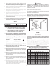
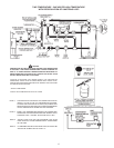
• Drill max. 5/16” hole in breeching as close as possible to
ue connection on heater to install stack thermometer and
combustion analyzing equipment, see Figure 4.
• You are now ready to begin the burner start-up procedure.