


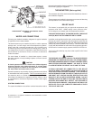

5
Continued manual resetting of high limit control, preceded by
higher than usual water temperature is evidence of high limit
switch operation. The following are possible reasons for high
limit switch operation.
• A malfunction in the thermostatic controls would allow the gas
valve to remain open causing water temperature to exceed the
thermostat setting. The water temperature would continue to
rise until high limit switch operation.
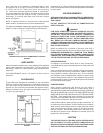
• An improper thermostat setting for a short repetitive usage
pattern may lead to a stacking effect. This causes a temperature
gradient increasing from the bottom to the top of the tank. It
is possible that the water at the high limit switch sensor could
reach its maximum temperature before the water temperature
at the thermostat reaches the dial setting, causing the high limit
switch to activate.
• A warming of ambient conditions associated with seasonal
change could magnify the stacking process described above
to the point where high limit switch operation would occur.
Contact your dealer or servicer if continued high limit switch
operation occurs.
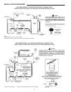
DISHWASHING MACHINE REQUIREMENT
All dishwashing machines meeting the National Sanitation
Foundation requirements are designed to operate with water
ow pressures between 15 and 25 pounds per square inch.
Flow pressures above 25 pounds per square inch, or below
15 pounds per square inch, will result in improperly sanitized
dishes. Where pressures are high, a water pressure reducing or
ow regulating control valve should be used in 180°F (82°C) line
to the dishwashing machine, and should be adjusted to deliver
water between these limits.
The National Sanitation Foundation also recommends circulation
of 180°F (82°C) water. Where this is done, the circulation
should be very gentle so that it does not cause any unnecessary
turbulence inside the water heater. The circulation should be just
enough to provide 180°F (82°C) water at the point of take-off to
the dishwashing machine. Adjust ow by means of the plug cock
in the circulating line.
INSTALLATION INSTRUCTIONS
REQUIRED ABILITY
INSTALLATION OR SERVICE OF THIS WATER HEATER
REQUIRES ABILITY EQUIVALENT TO THAT OF A LICENSED
TRADESMAN IN THE FIELD INVOLVED. PLUMBING, AIR
SUPPLY, VENTING, GAS SUPPLY AND ELECTRICAL WORK ARE
REQUIRED. NOTE: AUTHORIZED START-UP IS REQUIRED.
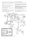
UNCRATING
The heater is shipped in standard form for vertical venting with a
barometric draft control assembly in a separate carton.
Optional horizontal vent models are shipped with one (1) exhaust
vent hood and one (1) ue reducer in a separate carton. Optional
direct vent models are shipped with two (2) vent hoods in separate
cartons. The exhaust vent hood carton contains one (1) exhaust
vent hood and one (1) ue reducer. The intake vent hood carton
contains one (1) intake vent hood and one (1) inlet adapter. All
parts should be installed as received without alteration.
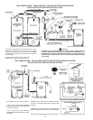
LOCATING THE HEATER
When installing the heater, consideration must be given to
proper location. Location selected should be as close to the
stack chimney as practicable, with adequate air supply and as
centralized with the piping system as possible.
WARNING
THERE IS A RISK IN USING FUEL BURNING APPLIANCES SUCH
AS GAS WATER HEATERS IN ROOMS, GARAGES OR OTHER
AREAS WHERE GASOLINE, OTHER FLAMMABLE LIQUIDS OR
ENGINE DRIVEN EQUIPMENT OR VEHICLES ARE STORED,
OPERATED OR REPAIRED. FLAMMABLE VAPORS ARE HEAVY
AND TRAVEL ALONG THE FLOOR AND MAY BE IGNITED
BY THE HEATER’S IGNITER OR MAIN BURNER FLAMES
CAUSING FIRE OR EXPLOSION. SOME LOCAL CODES PERMIT
OPERATION OF GAS APPLIANCES IF INSTALLED 18 INCHES
OR MORE ABOVE THE FLOOR. THIS MAY REDUCE THE RISK
IF LOCATION IN SUCH AN AREA CANNOT BE AVOIDED.
THE HEATER SHALL BE LOCATED OR PROTECTED SO IT IS NOT
SUBJECT TO PHYSICAL DAMAGE BY A MOVING VEHICLE.
WARNING
FLAMMABLE ITEMS, PRESSURIZED CONTAINERS OR ANY
OTHER POTENTIAL FIRE HAZARDOUS ARTICLES MUST
NEVER BE PLACED ON OR ADJACENT TO THE HEATER. OPEN
CONTAINERS OF FLAMMABLE MATERIAL SHOULD NOT BE
STORED OR USED IN THE SAME ROOM WITH THE HEATER.
THE HEATER MUST NOT BE LOCATED IN AN AREA WHERE
IT WILL BE SUBJECT TO FREEZING.
LOCATE IT NEAR A FLOOR DRAIN. THE HEATER SHOULD
BE LOCATED IN AN AREA WHERE LEAKAGE FROM THE
HEATER OR CONNECTIONS WILL NOT RESULT IN DAMAGE
TO THE ADJACENT AREA OR TO LOWER FLOORS OF THE
STRUCTURE.
WHEN SUCH LOCATIONS CANNOT BE AVOIDED, A SUITABLE
DRAIN PAN SHOULD BE INSTALLED UNDER THE HEATER.
Such pans should be fabricated with sides at least 2” (50.8 mm)
deep, with length and width at least 2” (50,8 mm) greater than the
diameter of the heater and must be piped to an adequate drain.
THE PAN MUST NOT RESTRICT COMBUSTION AIRFLOW.
Water heater life depends upon water quality, water pressure
and the environment in which the water heater is installed. Water
heaters are sometimes installed in locations where leakage may
result in property damage, even with the use of a drain pan piped
to a drain. However, unanticipated damage can be reduced or
prevented by a leak detector or water shut-off device used in
conjunction with a piped drain pan. These devices are available
from some plumbing supply wholesalers and retailers, and detect
and react to leakage in various ways:
• Sensors mounted in the drain pan that trigger an alarm or turn
off the incoming water to the water heater when leakage is
detected.
• Sensors mounted in the drain pan that turn off the water supply
to the entire home when water is detected in the drain pan.
• Water supply shut-off devices that activate based on the water
pressure differential between the cold water and hot water pipes
connected to the water heater.
• Devices that will turn off the gas supply to a gas water heater
while at the same time shutting off its water supply.