


27
GENERAL INFORMATION
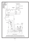
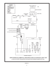
POWER BURNER
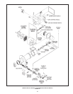
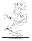
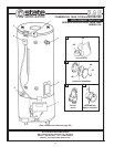
The initial start-up procedure of the gas power burner is provided
on page 18 thru 21. Refer to Figure 12, burner exploded view for
burner components location.
The sequence of operation of the power burner is provided on
page 15. For detailed Power Burner Operation, Maintenance
and Troubleshooting refer to the separate Power Burner Manual
provided with this water heater.
THERMOSTAT
It is suggested the thermostat be turned to the lowest setting,
which satises the hot water requirements of the system. This
helps minimize scale formation in the heater.
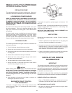
HIGH LIMIT
The high limit (not adjustable) is factory set to cutout at 205°F
(96°C). The high limit switch must be manually reset by depressing
the reset button on front of the control when water temperature
drops to about 180°F (82°C).
GAS AND AIR SUPPLY SPECIFICATIONS TABLE 10
Model GPG/GPV-540A GPG/GPV-650A GPG/GPV-750A
Min. Dynamic Gas
Supply Line 8” w.c. (2 kPa) When heater is ON
Pressure
Max. Static Gas
Supply Line 14” w.c. (3.5 kPa) When heater is OFF
Pressure
Gas Manifold
Pressure
Gas Orice Size 1/2” 11/16” N/A
Air Inlet Damper
Dial Setting
Combustion
Emissions
Range
* Note: Flue gas excess O
2
below 3% may cause combustion
chamber premature failure; ue gas excess O
2
above 7%
may cause rough operation or incomplete combustion. Final
manifold pressure settings should be based on ue O
2
/CO
2
reading!
** Note: Air inlet damper setting needs to be adjusted at eld for
direct vent and/or high elevation installations.
MAINTENANCE
GENERAL
KEEP APPLIANCE AREA CLEAR AND FREE FROM COMBUSTIBLE
MATERIALS, GASOLINE AND OTHER FLAMMABLE VAPORS
AND LIQUIDS. (SEE WARNING PAGE 6).
Water heater maintenance includes periodic tank ushing and
cleaning, and removal of lime scale. The power burner should
be inspected and adjusted to maintain proper combustion. Refer
to the following table. A periodic inspection of the venting system
should be made. Where used the water heating system circulating
pump should be oiled.
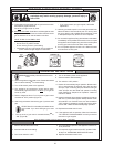
MAINTENANCE SCHEDULE
Following are the instructions for performing some of the
recommended maintenance. Power burner inspection and
adjustment should be performed by a competent technician.
MAINTENANCE SCHEDULE
Component Operation Interval Required
Sediment
Tank Removal Monthly Flushing
Lime Scale UN-LIME®
Removal Semi-Annually Delimer
Relief Valve Inspect Semi-Annually
SAE No. 20
Circulating Pump(1) Oiling Four Months non-detergent
motor oil
Clean Inlet
Power
Burner
Blower Screen and As Required Soft Brush
Blower Wheel
Power Burner and
Ignition Device(2) Inspection Semi-Annually
Make sure gate
Barometric Damper Inspect Every 3 swings freely,
Months no spillage
into room
Flue Cleaning As Required Wire Brush
Every 3 Joints should
Vent System Inspect Months be sealed
(1) If furnished with oiling provisions.
(2) If ange gasket is damaged, it must be replaced.
ELECTRICAL SERVICING
CAUTION
LABEL ALL WIRES PRIOR TO DISCONNECTION WHEN
SERVICING CONTROLS. WIRING ERRORS CAN CAUSE
IMPROPER AND DANGEROUS OPERATION.
VERIFY PROPER OPERATION AFTER SERVICING.
FLUSHING
1. Turn off the heater electrical disconnect switch.
2. Open the drain valve and allow water to ow until it runs
clean.
3. Close the drain valve when nished ushing.
4. Turn on the heater electrical disconnect switch.
Flue Gas O2: 5 - 6.5%**
(or CO2 reading 8 - 9%)
4.7”w.c.
(1.1
kPa)
(Ref.)*
4.7”w.c.
1.1
kPa)
(Ref.)*
4.7”w.c.
(1.1 kPa)
(Ref.)*
4.5** 5.6**
3**