


32
5. As soon as the pilot gas valve is energized, check for the
burner pilot flame through the burner peek-hole. If the pilot
flame is established inside the burner, then proceed to
Step 6.
• Turn the burner switch to “OFF” position for at least one minute
to reset the heater.
• Check for 24V between “PV” terminal and “MV/PV” terminal
after 45 seconds prepurge cycle (this 24V may only last
15 seconds starting after 45S prepurge). If there’s no 24V at
the “PV” terminal ever, and there’s 24V at “24V” terminal, the
Honeywell flame control module needs to be replaced.
• If 24V is detected for a period of 15 seconds, check for the
changes of gas supply line pressure when the pilot gas valve
is energized. If no visible pressure change during the pilot
ignition period, check for loose connection of the pilot valve or
a defective pilot gas valve.
• Adjust the pilot gas regulator setting during the pilot ignition
period (15 seconds). Do not set too much or too little pilot
gas. This adjustment should only be performed during the 15
seconds ignition period. A clockwise or counter-clockwise 0.5
to 1 turn should be able to correct the problem. Refer to burner
manual for detailed pilot gas setting procedure.
• If still no pilot flame inside the burner, check for the spark
ignitor wiring, ignitor tip location and visually check the
spark (burner pilot assembly needs to be taken out for the
visual check). Refer to the burner manual for detailed spark
ignition troubleshooting procedures.
6. Pilot ame established but not detected by the ame control
module. Use Micro Amp meter to measure ame signal during
the pilot ignition period. Refer to burner manual for testing
procedures.
• If pilot flame is confirmed visually through the burner
peek hole, and the flame signal is zero, the thermal-cutoff
safety switch (mounted nearby the flame rod, inside the
burner mixing chamber) may be broken or check for loose
wire connections or low gas switch (mounted inside control
panel) may be broken. If the thermal cutoff switch or low
gas switch is broken (by checking the switch continuity),
the switches must be replaced before the heater can
operate again.
• If it’s confirmed that the thermal cutoff switch is damaged
(open), call the State Technical Center to analyze the
root cause (too lean combustion) and proper gas/air ratio
adjustment. Flashback will cause the thermal cutoff switch
broken (open).
• If the ame signal is not zero but below 1µA, relocate ame rod
or replace ame rod will be required. Refer to burner manual
for detailed procedure of replacing ame rod.
MOTOR RUNS CONTINUOUSLY, BURNER LIGHTS ON
MOMENTARILY THEN LOCKS OUT OR EXCESSIVE
ON/OFF CYCLE
Under this condition, the burner will start the purge cycle again,
then pilot ignition and main ame cycle. If main ame cannot be
sustained:
1. Make sure main manual gas valve (right after the Robertshaw
gas valve) is fully open;
2. Check for 24V at the Robertshaw gas valve when the main
gas light is on. If there’s no 24V at the valve, check loose wire
connection.
3. Check for gas supply line pressure. The gas line pressure
before the valve should be maintained at minimum
8” w.c. when main flame is “ON”. If the gas line pressure
drops below 8” w.c. (2 kPa), the service regulator pressure
setting must be increased to keep 8” w.c. (2 kPa) minimum
gas pressure. After adjusting the gas regulator setting,
turn off the heater, make sure the gas line pressure does
not exceed 14” w.c. (3.5 kPa) if it does exceed 14” w.c.
(3.5 kPa) static pressure, the gas supply line size must be
increased accordingly to avoid gas line pressure exceeding
14” w.c. (3.5 kPa)
4. Check the gas valve manifold pressure (refer to Table 10),
see ADJUSTMENT PROCEDURE to adjust the manifold
pressure.
5. Check for defective gas valve for failing to open or shut
off.
6. Verify that the air supply is adequate. The air inlet screen
or blower wheel may be restricted.
7. Check the installation for proper ventilation, see AIR
REQUIREMENTS.
8. Verify the air switch setting is not too high.
9. Check the venting system for the correct sizing, excessive
or insufficient draft, and proper operation of the barometric
draft control, see VENTING.
NOISY BURNER OPERATION
1. Check for flue gas excess O2 or CO2 reading (refer to
Table 10). If combustion is too lean (flue gas O2 reads more
than 7.5%), the combustion flame front may not be stable,
which will cause noisy operation. See ADJUSTMENT.
2. Check the venting system for the correct sizing, excess or
insufficient draft, and proper operation of the barometric
draft control, see VENTING.
3. If the burner operation is still noisy, then remove the burner,
examine the burner diffuser, blast-tube tip, anti-flashback
corrugated tube, center mixing, refer to the burner manual
for details.
GAS FAILS TO SHUT OFF
Check for defective gas valve or thermostat. If operation is
incorrect, replace.
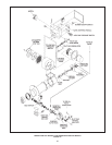
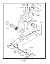
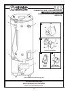
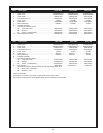
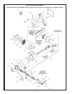
REPLACEMENT PARTS
R epl ac eme nt pa rts ma y b e o rd ere d t hr oug h S ta te
dealers, unauthorized servicers or distributors. Refer to
the Yellow Pages for where to call or contact the State Water
Heaters, 500 Lindahl Parkway, Ashland City, TN 37015, 1-800-
821-2017 or visit our website at www.statewaterheaters.com
When ordering parts be sure to state the quantity, part number
and description of the items including the complete model
and serial number as it appears on the product. Refer to the
parts list for more information.