


29
ABOVE ALL, DO NOT PLUG THE TEMPERATURE AND
PRESSURE RELIEF VALVE. THIS IS NOT A SOLUTION AND
CAN CREATE A HAZARDOUS SITUATION.
CIRCULATING PUMP
The water heating system may include a circulating pump. Where used,
it should be lubricated as directed by the circulator manufacturer.
LOW EMISSION POWER BURNER
KEEP THE AREA AROUND THE BURNER CLEAR AND FREE
OF COMBUSTIBLE MATERIALS, GASOLINE OR OTHER
FLAMMABLE LIQUIDS OR VAPORS. DO NOT OBSTRUCT
BURNER AIR OPENINGS OR VENTILATION GRILLES FOR
COMBUSTION AIR. REMOVE LINT ACCUMULATION FROM
AIR INTAKE GRILL.
The main burner ame should be visually checked once a year
for proper operation. This can be observed through the “peep
sight” port on the burner mounting plate. Burner ame should
be kept blue.
At least annually, contact a qualied service agency for burner
cleaning and other routine maintenance. For burner related
Maintenance Schedule, Troubleshooting, Flame Rod, Ignitor,
Thermal Cut-Off Switch Replacement Procedures, use burner
Operation & Maintenance Manual provided with this heater.
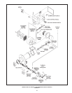
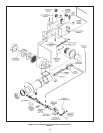
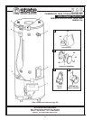
CLEANING FLUES
The following describes how to gain access to the tank ues for
cleaning if necessary.
1. Turn off the heater electrical disconnect switch.
2. Remove the vent connector from on top of the heater.
3. Remove the jacket top from the heater by taking out the screws
and lifting it off.
4. Remove the insulation from the top of the heater.
5. Remove the inner cover by taking out the pipe collar around
the water inlet and outlet nipple.
6. The ue bafes may now be removed by lifting out.
7. Using a wire brush, a nylon brush must not be used, remove
soot from ue passages in heater tank.
CAUTION
brush does not come in contact with neither the combustion
part of the combustion chamber, as damage could occur.
diameter.
8. Upon completion of cleaning, return heater to operation by
following this procedure in reverse.
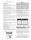
BAROMETRIC DRAFT CONTROL
- FOR GPG MODELS
The heater is equipped with a double acting barometric draft
control as shown in Figure 15. The damper gate must pivot freely
in the ring guides.
FIGURE 15
To test gate for operation, gently tap gate and observe. DO
NOT OIL.
Adjust the number of counter-weight washers on the control to
maintain a negative draft of 0.02” to 0.04” w.c. in the venting. See
VERTICAL VENTING, page 8.
NOTE THAT THIS CONTROL WILL ONLY BE PRESENT IN A
VERTICAL VENT INSTALLATION.
VENT SYSTEM
Examine the vent system every 3 months. Points of inspection
are as follows:
1. Check for obstructions and/or deterioration of vent piping and
vent hood. Replace immediately where needed.
2. Vent pipe and vent hood screen should be cleaned of foreign
material and soot. The screen is located inside the vent hood
outlet and is accessible from the outside of the hood. Do not
reach inside the vent when the heater is in operation.
3. Check all vent system connections for leakage and re-seal as
required using Hi Temp Silicone sealer or equivalent.
CHECKLIST AND SERVICE
INFORMATION
IMPORTANT
The installer may be able to observe and correct certain problems
which might arise when the unit is put into operation or when it is re-
red after a prolonged shutdown. HOWEVER, it is recommended
that only qualied servicemen, using appropriate test equipment,
be allowed to service the heater.
BE SURE TO TURN OFF THE ELECTRICITY WHENEVER
POSSIBLE OR APPROPRIATE WHILE CHECKING EQUIPMENT.
BURNER OPERATIONAL PROBLEMS
1. Refer to TROUBLESHOOTING for comprehensive service
information provided with both heater and burner manuals.
NOT ENOUGH OR NO HOT WATER
1. Be certain the electrical disconnect switch serving the water
heater is in the ON position.