


11
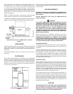
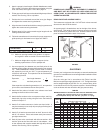
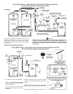
5. Attach a properly sized length of Selkirk Metalbestos model
PS or model G venting to the exhaust vent adapter using the
inner vee bands, see Figures 7 and 7B on page 10.
6. Fill the grooves in both inner vee bands with high-temp silicone
sealant, Dow Corning 736 or equivalent.
7. Position the inner vee bands around the inner pipe anges
and tighten the screws securing the bands.
8. Align the outer channel band with the outer pipe grooves and
tighten the screws securing the bands.
9. Repeat steps 6-8 for each successive pipe length until the
venting reaches the heater.
10. Follow the manufacturer’s instructions for proper support and
guide spacing for horizontal runs of pipe, see Table 6.
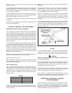
TABLE 6.
Vent Diameter S F
8” - GPV -540A, 650A & 740A 15’ 3” 7’ 6”
S = Maximum spacing between two guides or a support
and a guide in either a vertical or horizontal direction.
F = Maximum height above a guide or support for free
standing system above a roof or parapet wall.
11. Use an expansion joint between any two xed points in the
exhaust venting system wherever the expansion may exceed
1/4”. Selkirk Metalbestos model PS and model G venting
will expand by one inch per 100°F in gas temperature per
100 feet of vent length. The expansion can be calculated by
the following formula:
Expansion, Vent length between 5
Inches two xed points, feet 100
If the expansion calculated is greater than 1/4”, an expansion
joint must be used between the two xed points.
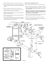
12. Attach the ue reducer included in the exhaust vent hood
package to the ue collar on the heater.
13. Attach the ue reducer to the vent system using a seal ring.
Attach this ring to the venting using the inner vee bands as
outlined in Steps 5-7.
14. Attach 8” air-intake connector to intake vent hood collar. It
may be necessary to use a slip-slip coupling to t the pipe to
the intake vent hood.
15. Attach 8” air-intake connector back to the 6” burner air inlet
with 8” x 6” reducer. Prime and cement each joint to assure
gas-tight construction.
16. Seal all joints at the vent hoods with silicone sealant. Also
seal the joints at the ue collar and air inlet adapter. Joint
on the exhaust side must be sealed with high-temp silicone
sealant, Dow Corning 736 or equivalent.
WARNING
PRIMERS AND CEMENTS ARE EXTREMELY FLAMMABLE,
AND MUST NOT BE STORED OR USED NEAR HEAT OR
OPEN FLAME. ALLOW ADEQUATE CURING TIME BEFORE
OPERATING HEATER.
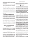
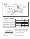
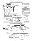
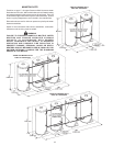
DRAIN VALVE AND ACCESS PANELS
The heaters are equipped with a 3/4” NPT drain valves mounted
above and to the left of the burner.
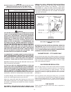
An access panel is located above and to the right of the burner,
see Figure 8. This panel covers the cleanout opening in the tank
which is sealed by a gasket and cover. Another cleanout access
panel is located towards the back of the heater.
FIGURE 8.
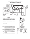
GAS PIPING
Contact your local gas service company to ensure that adequate
gas service is available and to review applicable installation codes
for your area.
Size the main gas line in accordance with Table 9 and 9A.
Minimum required gas supply pipe size is 1 1/4”. The gures shown
are for straight lengths of pipe at 0.5 in. w.c. pressure drop, which
is considered normal for low pressure systems. Note that ttings
such as elbows and tees will add to the pipe pressure drop.
TABLE 9
MAXIMUM CAPACITY OF PIPE IN CUBIC FEET OF GAS PER HOUR
(Based upon a Pressure Drop of 0.5 inch Water Column
LENGTH
IN Nominal Iron Pipe Sizes, Inches
FEET 1/2” 3/4” 1” 1 1/4” 1 1/2” 2” 2 1/2” 3” 4”
10 175 360 680 1400 2100 3960 6300 11000 23000
20 120 250 485 950 1460 2750 4360 7700 15800
30 97 200 375 770 1180 2200 3520 6250 12800
40 82 170 320 660 990 1900 3000 5300 10900
50 73 151 285 580 900 1680 2650 4750 9700
60 66 138 260 530 810 1520 2400 4300 8800
70 61 125 240 490 750 1400 2250 3900 8100
80 57 118 220 460 690 1300 2050 3700 7500
90 53 110 205 430 650 1220 1950 3450 7200
100 50 103 195 400 620 1150 1850 3250 6700
125 44 93 175 360 550 1020 1650 2950 6000
150 40 84 160 325 500 950 1500 2650 5500
175 37 77 145 300 460 850 1370 2450 5000
200 35 72 135 280 430 800 1280 2280 4600
= x