


31
20, and the troubleshooting section of burner manual before
continuing.
Make sure the appliance is connected to a 120 Vac power supply,
burner switch is “ON” and manual gas valve is in the “ON” position,
and all electrical connections are secure before continuing to
troubleshoot this appliance.
MOTOR WILL NOT RUN
1. Conrm 120 Vac. Also, to verify correct polarity, check for
120 Vac between black wire and G.
If there is no voltage, check for a loose connection or open
switch at the high limit or thermostat.
2. If there is 120 volts between black wire and white wire, check
for loose connections or a locked rotor. If the rotor cannot be
freed the motor and blower assembly must be replaced.
BURNER LOCKOUT ONCE IN A WHILE
Under this condition, the burner operates properly for days, and
burner lockout occurs once in a while. The root causes for the
burner occasional lockout include: (1) Gas inlet pressure too low;
(2) Condensation over the ignitor area; (3) the pilot ame is too
weak to light the main ame reliably; (4) the pilot air/gas ratio is
out of range causing pilot ame to be unreliable.
1. Turn burner switch to “OFF” position and turn off the main
gas valve (Robertshaw
®
).
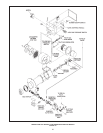
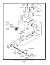
2. Install manometers for gas inlet pressure, manifold pressure,
and pilot gas pressure, see Figure 12 for the pressure ports
location).
3. Check for the gas inlet pressure, reset the service regulator
(if required) to get 9” w.c. (2.2 kPa) - 10” w.c. (2.4 kPa) inlet
pressure while the burner is in the “OFF” position.
4. Turn the burner “ON”,
• Take blower pressure at the pressure port during the
purge cycle, see Figure 12 for location.
• Take the pilot gas pressure at the same pressure port
during the ignition period (following 45 seconds purge
cycle).
• The pilot gas pressure should be 0.6” - 0.9” w.c. higher
than blower pressure, if not, adjust the pilot gas regulator
(during the ignition cycle, see Figure 12.
• If burner lights on during the ignition cycle, cycle the
unit on/off several times to ensure pilot system is
reliable. Turn off the burner, then follow Step 6.
5. Turn the burner “OFF”, follow burner manual instructions to
remove the pilot assembly (also refer to Figure 12 in this
manual) and procedures to check pilot assembly. Items to
check for the pilot system include:
• Check for condensation over ignitor area.
• Check for the ignitor gap (1/8” - 3/16”).
• Check for the thermal cutoff continuity by ohm meter,
replace it if the thermal cutoff is open.
• Check for the low gas pressure switch by ohm meter
(while pilot gas pressure is 7” w.c. [1.7 kPa] or higher).
• Check for the continuity between the ame rod and
sensor connection at Honeywell ame control module
by the ohm meter.
• Check for ignitor wire connections and spark leakage
(call AOS service center for steps of spark leakage
checking).
• Following burner manual instructions to re-install the
pilot assembly.
6. Turn on the Robertshaw gas valve, turn the burner switch to
“ON” position. Cycle the heater ON/OFF several times to ensure
the problem is solved.
MOTOR RUNS CONTINUOUSLY, PREPURGE TIME ELAPSES BUT
MAIN FLAME NOT ESTABLISHED (BURNER LIGHT NEVER ON)
1. When the heater is rst installed, gas line must be purged
properly prior to start-up. This heater is equipped with a ame
control module that only allows one “trial for ignition” for
15 seconds and locks out if no ame signal is detected. For
initial start-up, two or more resets may be required to ensure
that all the air has been purged from the gas pilot line. To reset
the heater, turn the burner power switch to “OFF” position for
at least one minute, then turn it back “ON”.
2. Check for gas supply line manual valves in “ON” position, and
line pressure. Make sure the pilot manual gas cock (nearby
the main gas valve) is fully open.
3. After the 45-seconds prepurge cycle, the pilot gas valve
(mounted on the panel) “click” sound should be heard. If you
hear the pilot gas energized, proceed to Step 5.
4. Check 24 Vac control circuit in the following systematic
approach:
• Check for 24V between “24V” and “GND” of Honeywell Flame
Control Module, which is located inside the burner control panel.
If voltage is OK, proceed to Step 5.
• If there’s no voltage, check for 24V between the air switch
“COM” terminal and GND (the air switch is mounted on the
control panel, the switch cover needs to be removed to access
the wiring terminal “COM” and “NO”). If there’s no 24 V, check
for a loose connection between the 24V transformer and air
switch, or a defective transformer.
• If there’s 24V at “COM” terminal, check for 24V between
the air switch terminal “NO” (normally open) and GND. If
there’s no 24V, the air switch pressure may be set too high
or a defective air switch or loose connections of pressure
sensing tubings. To lower the air switch setting, make sure
the blower is running and blower wheel and air inlet are free
from dirt, counterclockwise turn the switch setting-screw
until the switch is closed. Call the State Technical Center
before you reset the switch.
• If there’s 24V at “NO” terminal of the air switch, check for 24V
at the air intake pressure switch connectors, (this switch is only
supplied for direct vent systems). If there’s no 24V at the switch
connectors, check for loose connections, air intake blockage,
or a defective air switch.
• Do not proceed to Step 5 unless 24V is detected at “24V”
terminal of the Honeywell Module.