


7
Heater must be protected from freezing downdrafts during
shutdown periods.
The GPG 540A, 650A and 750A water heater are classied as a
category I appliance (non-positive vent pressure, non-condensing)
when installed with the supplied barometric draft control assembly
in a vertical vent installation.
The GPV 540A through 740A heater is classied as a category III
appliance (positive vent pressure, non-condensing) when installed
with supplied sidewall vent kits or direct vent kit.
All regulations pertaining to the venting of these heaters must
be followed.
The following vent installation instructions cover vertical, horizontal,
and direct vent applications.
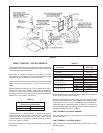
VERTICAL VENTING - FOR GPG MODELS
BAROMETRIC DRAFT CONTROL ASSEMBLY
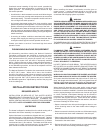
A double-acting barometric draft control assembly is provided with
any unit intended for chimney venting. The purpose of this draft
control is twofold. During downdrafts it acts as a pressure relief
control to prevent the downdraft from blowing into the heater. It
also allows for makeup air to enter the chimney without being
drawn through the heater. In both cases the control prevents the
heater performance from being adversely affected by conditions
within the chimney.
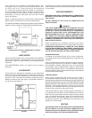
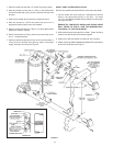
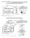
The draft control assembly must be installed without alteration.
This assembly is factory adjusted for horizontal application only
and must be attached to the heater as shown in Figure 4. The
direction in which the outlet to the draft controls assembly faces
is arbitrary. The assembly must be tted to the jacket cover such
that it is plumb and level to the ground. Fasten the draft control
assembly to the top cover using sheet metal screws at three
locations, or more, as required.
Damper or other obstructions must not be installed between the
heater and the barometric draft control assembly.
Do not adjust settings on gate.
When installed, the damper gate must pivot freely in the ring
guides. This gate will automatically adjust to regulate the chimney
draft imposed on the heater.
VENT CONNECTIONS
Vent connections must be made to an adequate stack or
chimney. Refer to the National Fuel Gas Code or to the vent pipe
manufacturer’s gas vent and chimney sizing table to properly
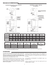
design and size the venting system. Refer to Table 1 for the vent
pipe size required for installation to the barometric draft control
assembly outlet.
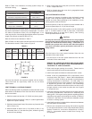
TABLE 1.
Model Flue Outlet
GPG-540A 9” (228.6 mm)
GPG-650A 9” (228.6 mm)
GPG-740A 9” (228.6 mm)
Single-wall or type B venting may be used with these heaters in
vertical vent installations. All local and utility regulations on venting
must be followed.
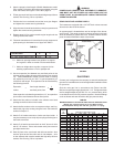
NOTE: A NEGATIVE DRAFT MUST BE MAINTAINED IN
VENTING.
A negative draft of 0.02” to 0.04” w.c. Must be maintained in
venting system. Measure draft at the location illustrated in
Figure 4. Adjust the control counter-weights if necessary as shown
in the MAINTENANCE portion of this manual.
Where an existing chimney or vent is to be used, be sure that the
chimney or vent has adequate capacity for the number and sizes
of gas appliances being vented through it. Inspect the chimney
or vent and remove all soot or other obstructions, which will retard
free draft.
Vent connectors making horizontal runs must have a minimum
upward slope toward the chimney or vent of ¼ inch per foot. Vent
connector length should be kept as short as possible. Be sure
that the vent pipe does not extend beyond the inside wall of a
chimney, see Figure 4.
FIGURE 4.
In venting systems where a continuous or intermittent back
(positive) draft is found to exist, the cause must be determined and
corrected. In some cases, a special vent cap may be required.
WARNING
Failure to correct back drafts may cause air contamination
and unsafe conditions.
Do not connect the heater to a common vent or chimney with solid
fuel burning equipment. This practice is prohibited by many local
building codes as is the practice of venting gas red equipment
to the ductwork of ventilation systems.
Connectors shall not be connected to a chimney, vent or venting
system served by a power exhauster, unless the connection is
made on the negative pressure side of the exhauster.
Do not connect any heater vented by natural draft to any vent
serving mechanical draft equipment operating under positive vent
pressure such as category III or category IV appliances.
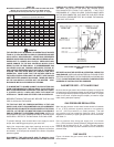
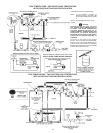
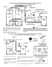
HORIZONTAL (SIDE-WALL) VENTING -
FOR GPV MODELS
An exhaust vent hood, vent hood and a ue reducer are supplied
with any unit intended for through-the-wall horizontal venting.
These parts must be installed without alteration. The vent hood
adapter is designed for use with Selkirk Metalbestos Model PS
or Model G venting, see Figure 7 on page 10.