


10
1. Shall be located not less than 12” (304.8 mm) above grade.
2. Shall be located not less than 3 (.9144 m) feet horizontally
from and not less than 3 feet (.9144 m) below an exhaust vent
terminal.
3. Shall not be located directly above an exhaust terminal.
4. Shall be located 12” (304.8 mm) above the snow line in
geographical areas where snow accumulates.
5. Shall be located not less than 7 feet 2.1 m) above grade when
adjacent to a public walkway.
6. Shall not be closer than 3 feet (.9144 m) from the inside corner
of an L - shaped structure.
7. Shall be located not less than 3 feet (.9144 m) horizontally or
3 feet (.9144 m) vertically from gas line, meter, or other gas
supply entering a structure, see Figure 6.
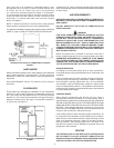
FIGURE 7.
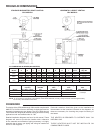
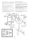
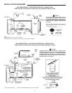
DIRECT VENT SYSTEM INSTALLATION
Plan the vent system backwards from the vent hood to the heater.
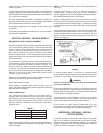
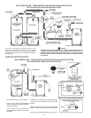
1. Use the inside wall cover plate as a template to mark two
holes in the appropriate places on the wall. Cut holes
1/2” (12.7 mm) larger to facilitate easy installation of vent hoods,
see Figures 6 and 7.
BEWARE OF CONCEALED WIRING AND PIPING INSIDE
WALL. REFER TO TABLE 3 FOR THE MAXIMUM WALL
THICKNESS “B” FOR EACH MODEL.
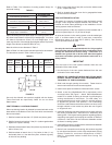
2. Slide hoods through openings from outside. Fasten hoods to
exterior wall with anchors and screws supplied.
3. Install cover plate and fasten to inside wall with 4 screws
4. Attach a seal ring (Selkirk Metalbestos Model SR or equivalent)
to the vent hood collar, see Figure 7.
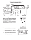
FIGURE 7B.