


99
Fig. 9-10
Fig. 9-9
Fig. 9-8
Fig. 9-11
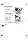
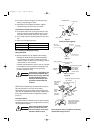
● Do not use a spanner to tighten the valve stem caps.
Doing so may damage the valves.
● Depending on the installation conditions, applying
excessive torque may cause the nuts to crack.
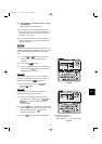
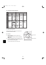
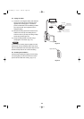
Precautions for Packed Valve Operation
● If the packed valve is left for a long time with the valve
stem cap removed, refrigerant will leak from the valve.
Therefore, do not leave the valve stem cap removed.
● Use a torque wrench to securely tighten the valve stem
cap.
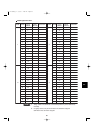
● Valve stem cap tightening torque:
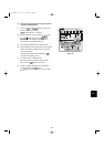
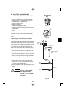
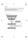
9-3. Insulating the Refrigerant Tubing
Tubing Insulation
● Thermal insulation must be applied to all unit tubing,
including the distribution joint (purchased separately).
* For gas tubing, the insulation material must be heat
resistant to 248°F or above. For other tubing, it must be
heat resistant to 176°F or above.
Insulation material thickness must be 13/32 in. or greater.
If the conditions inside the ceiling exceed DB 86°F and
RH 70%, increase the thickness of the gas tubing
insulation material by 1 step.
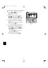
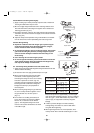
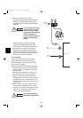
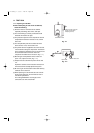
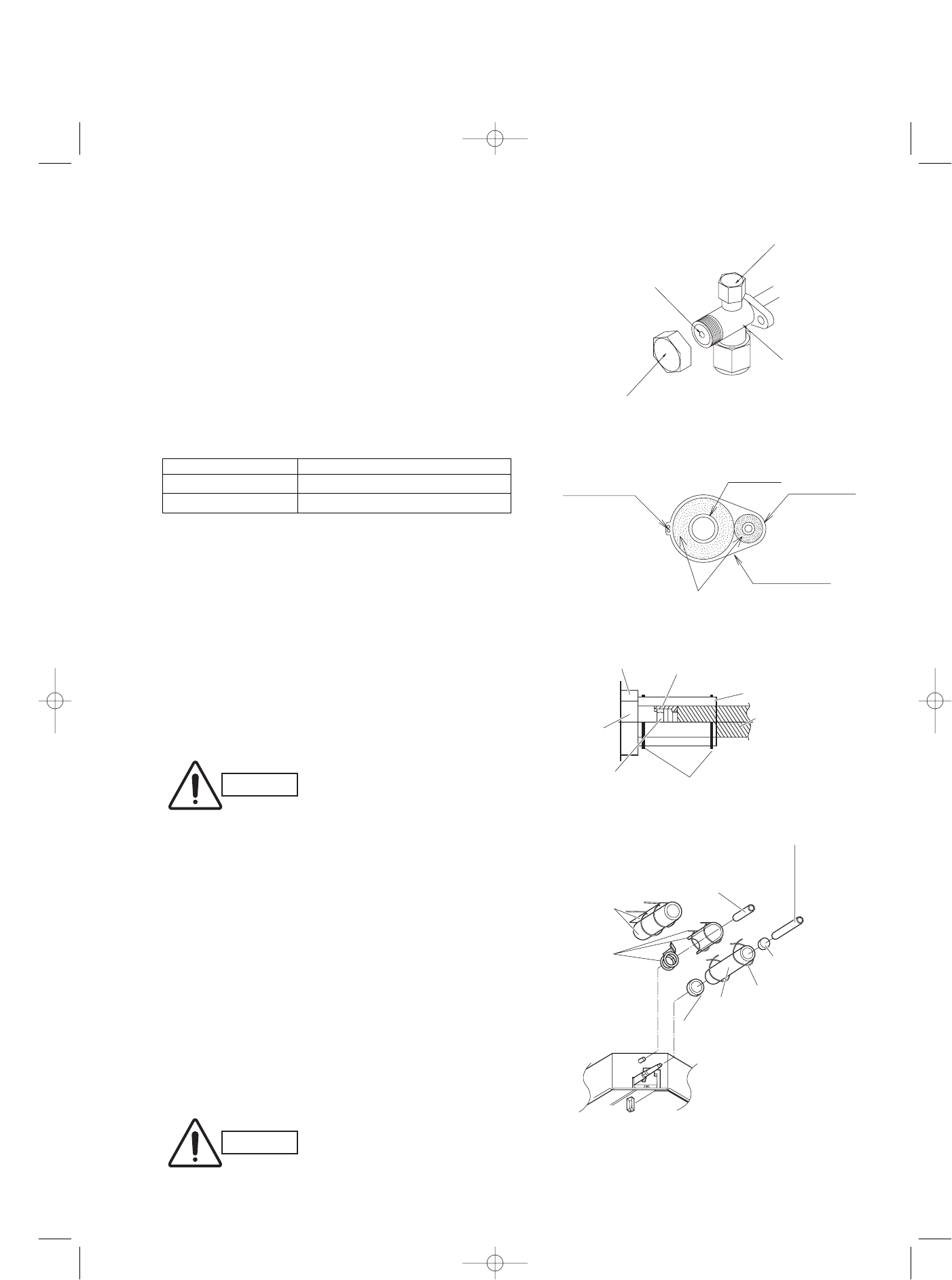
Taping the flare nuts
Wind the white insulation tape around the flare nuts at the
gas tube connections. Then cover up the tubing
connections with the flare insulator, and fill the gap at the
union with the supplied black insulation tape. Finally, fasten
the insulator at both ends with the supplied vinyl clamps.
(Fig. 9-10)
Insulation material
The material used for insulation must have good insulation
characteristics, be easy to use, be age resistant, and must
not easily absorb moisture.
CAUTION
CAUTION
Never grasp the drain or refrigerant connecting
outlets when moving the unit.
Unit side
insulator
Insulation tape (white)
(supplied)
Sealer (supplied)
Flare insulator (supplied)
Tube insulator
(not supplied)
Heat resistant
248ºF or above
Vinyl clamps (supplied)
Flare nut
The procedure used for
installing the insulator for
both gas and liquid
tubes is the same.
Seal
Flare
insulator
Vinyl
clamp
Insulation
tape
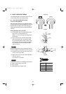
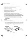
Refrigerant tubing and insulator
(not supplied)
Drain pipe and insulator
(not supplied)
Drain insulator
and clamp.
Large
(supplied)
Packing
clamp.
Small
hose band
(supplied)
2 tubes arranged together
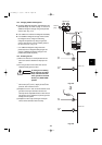
If the exterior of the outdoor unit
valves has been finished with a
square duct covering, make sure
you allow sufficient space to
access the valves and to allow
the panels to be attached and
removed.
Charging port 8 – 10 N • m (80 – 100 kgf • cm)
ø3/8" (Liquid side) 19 – 21 N • m (190 – 210 kgf • cm)
ø5/8
" (Gas side) 28 – 32 N • m (280 – 320 kgf • cm)
Inter-unit
control wiring
Gas tube
Liquid tube
Armoring tape
Insulation
Charging port
Valve stem cap
Valve stem
Main valve
Packed valve
After a tube has been insulated,
never try to bend it into a nar-
row curve because it can cause
the tube to break or crack.
07-115 SSHP_II 5/7/07 4:00 PM Page 99