


108
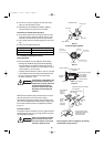
11-8. Examples of Wiring Diagrams
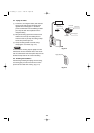
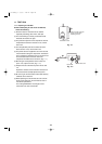
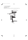
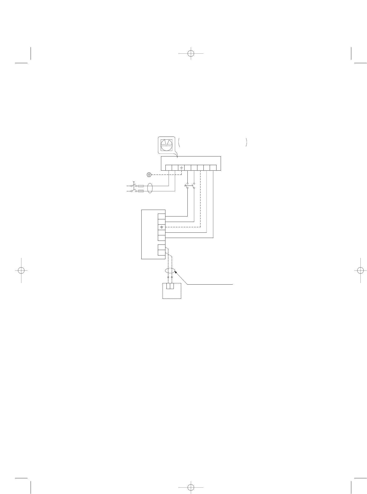
11-8-1. Basic wiring diagram 1
Single-type system
● Be careful to avoid miswiring when connecting the wires. (Miswiring will damage the units.)
1
2
12
0
L2
U1
RC
U2
L1 U2U1G
1
2
System address rotary switch
(Set to “0” at the time of shipment.)
Outdoor unit
Indoor
unit
Wired remote
controller
WHT
BLK
(Optional)
Remote controller wiring
(Field supply)
Ground
Power supply
Single-phase
230 / 208 V
Inter-unit power line
230 / 208 V, 60 Hz
Fig. 11-5
07-115 SSHP_II 5/7/07 4:00 PM Page 108