


X
70
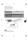
<RCS-SH80UA.WL>
4-Way Air Discharge Semi-concealed Type
(X Type)
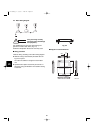
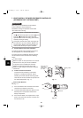
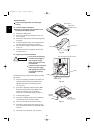
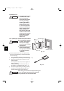
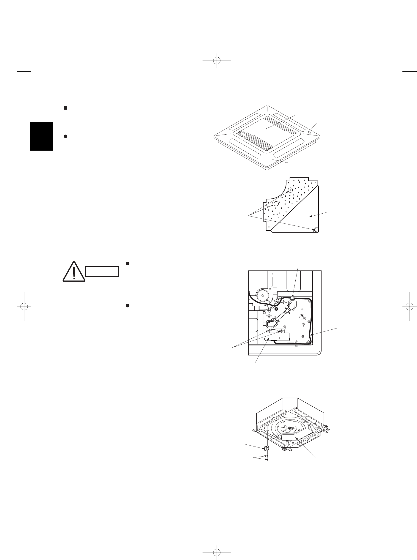
7-5. Indicator Section Installation
Remove the ceiling panel and indicator cover
and install the indicator section.
(1) Remove the ceiling panel.
(2) Remove the corner cover behind the mark sec-
tion. (3 screws)
(3) Remove the mark section inside the ceiling panel.
(2 screws)
(4) Install the indicator section in the location where
the mark section was attached. (2 screws)
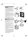
(5) Form the wire to match the panel ribs as shown
in Fig. 7-6.
(6) Install the corner cover. (Restrain the wire with
the corner cover.)
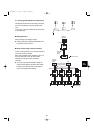
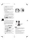
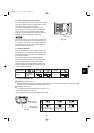
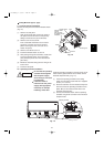
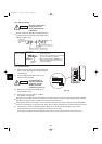
7-6. Operating Controller Installation
Do not twist the operating
controller wires together
with the power supply
wires. Doing so can result
in malfunction.
If electrical noise is induced
in the unit power supply,
take appropriate measures,
for example installing a
noise filter.
Install the operating controller at the indoor unit in
take
port section.
(1) Fasten the operating controller to the indoor unit
intake port section (electrical component box
opposite side) with the 2 accessory screws
(4 × L13/32 in.).
(2) Connect the operating controller 2 wires (WHT,
BLK) to the remote control wire (WHT) in the
electrical component box. (For details on
wiring, see “7-9. Electrical wiring” on page 72.)
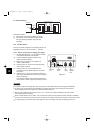
(3)Install the ceiling panel.
(4) Connect the indicator section and the operating
controller with the 6P connector (white).
(5) Form the wires with vinyl clamps and fasten.
(6) Connect the ceiling panel wiring connector (2P,
3P) to the body connector in the electrical compo-
nent box.
(7) For details on test operation, see “Test Run.”
CAUTION
Ceiling panel
Air intake grille
Mark section
(indicator section)
Fig. 7-5
Corner cover
3 screws
Fig. 7-6
2 screws
Indicator section
Wiring
Pass the wiring through under the shaft.
Fig. 7-7
Electrical
component box
Operating
controller
Screws
07-115 SSHP_II 5/7/07 4:00 PM Page 70