


12
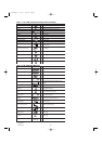
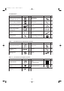
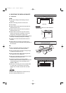
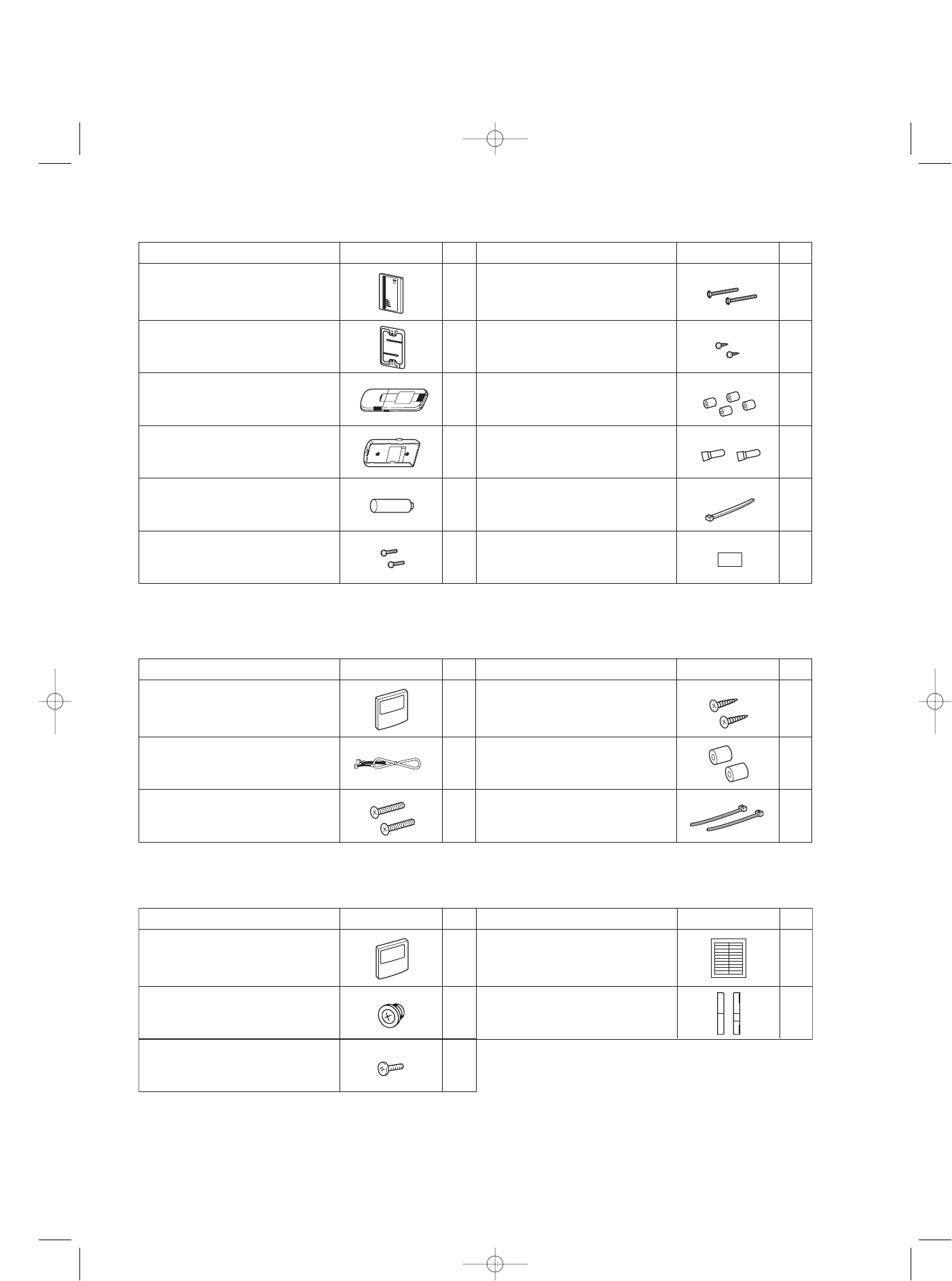
Table 1-7 (Accessories for the Timer Remote Controller)
Part Name Figure
‘Q’ty
Part Name Figure
‘Q’ty
Timer Remote Controller
1 Spacers 2
1Wood screws
2 Clamps
Machine screws
M4 × 1 in.
Connecting wiring
length 4 ft.
2
2
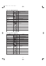
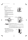
Table 1-8 (Accessories for the System Controller)
Part Name Figure
‘Q’ty
Part Name Figure
‘Q’ty
System controller 1 1
41
Rubber bushing
(7/8 in.)
Label
(Identification label)
2
Screws for fixture
(1-3/16 in.)
Label
(Terminal base label)
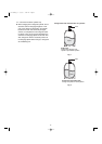
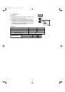
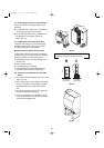
SYSTEM CONTROLLER IDENTIFICATION LABEL
ALL Central Control ALL RCU.
ZONE1 Central Control
ZONE1 RCU.
ZONE2 Central Control
ZONE2 RCU.
ZONE3 Central Control
ZONE3 RCU.
ZONE4 Central Control
*Please attach this label on surface of the lid after cleaning.
*If need to write down some detail, use magic marker.
ZONE4 RCU.
ALL ON
INPUT
ALL OFF
INPUT
COMMON
INPUT
COMMON
OUTPUT
OPERATION
STATE
OUTPUT
ALARM
OUTPUT
U1
U2
Inter-
unit
control
wiring
U2 Aux.
UNUSED
DC12V
FROM
INDOOR
UNIT PCB.
Small screws
M4 × 1-9/16 in.
Machine screws
M4 × 1 in.
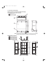
Ceiling installation paper pattern
(
3-3/4 × 2-1/32 in.
)
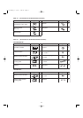
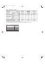
<RCS-BH80UA.WL>
Part Name Figure
‘Q’ty
Part Name Figure
‘Q’ty
12
Carrier for ceiling installation 1Wood screws 2
Wireless remote controller 1 Spacers 4
1 Wire joints 4
Batteries 2 Clamp
21
Separate type signal receiving unit
(comes with 7-7/8 in. wire)
Wireless remote controller
mounting cradle
1
07-115 SSHP_II 5/7/07 3:59 PM Page 12